6 disassembly, 7 assembly – Flowserve N-Series Worthington User Manual
Page 12
N-SERIES OF THRUST POT USER INSTRUCTIONS ENGLISH 07/14
Page 12 of 20
4.6 Disassembly
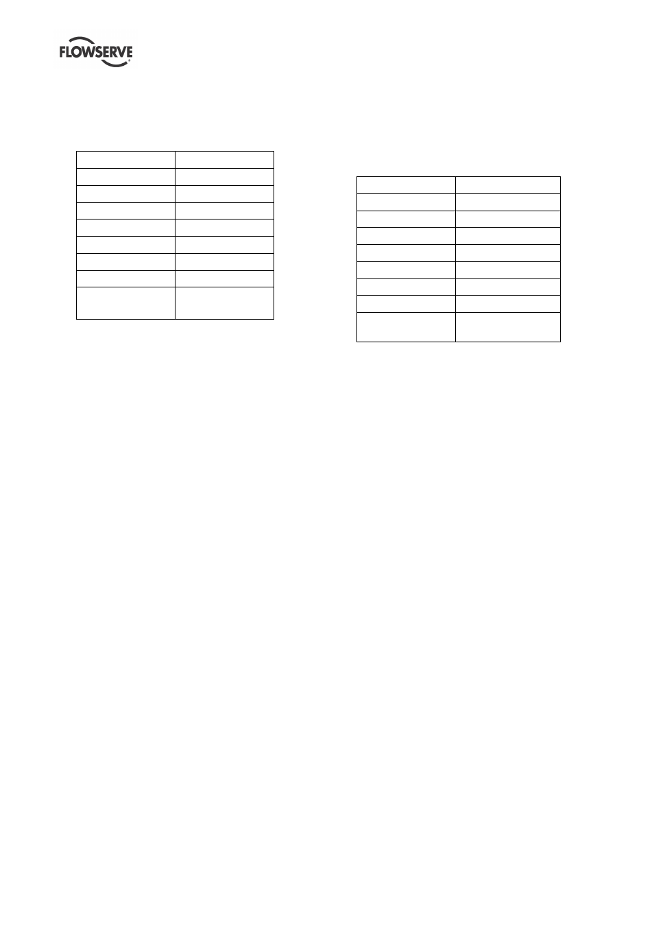
4.6.1 Dismantling of the thrust bearing
Thrust bearing No.
Bearing size
0 N
7210 BECBJ
1 N
7313 BECBJ
3 N
7315 BECBJ
4 N
7317 BECBJ
5 N
7318 BECBJ
6 N
7322 BECBM
7 N
7326 BCBM
8 N
7232 BCBM
7330 BCBM
4.6.1.1 Bearing housing 3N – 8N
1) Remove the bearing assembly consisting of the
thrust ball bearing [3013.1], bearing adaptor
sleeve [2471], spacer ring [2510] and the bearing
lock nut [3712] as a cartridge.
2) Open the bearing lock nut [3712] and pull off the
thrust ball bearing [3013.1]
4.6.1.2 Bearing housing 0N – 1N
1) Remove the bearing assembly consisting of the
thrust ball bearing [3013.1], bearing adaptor
sleeve [2471] and the bearing lock nut [3712] as
a cartridge.
Open the bearing lock nut [3712] and pull off the
thrust ball bearing [3013.1].
4.7 Assembly
Ensure threads, gasket and O-ring mating faces are
clean.
4.7.1 Assembly of the thrust bearing
Thrust bearing No.
Bearing size
0 N
7210 BECBJ
1 N
7313 BECBJ
3 N
7315 BECBJ
4 N
7317 BECBJ
5 N
7318 BECBJ
6 N
7322 BECBM
7 N
7326 BCBM
8 N
7232 BCBM
7330 BCBM
4.7.1.1 Bearing housing 3N – 8N
1) Heat up the first angular contact bearing, and put
it on the bearing adaptor sleeve [2471] as shown
in the section drawing.
2) Install the spacer ring [2510]. Warm up the other
two bearings and install it according to the
section drawing. Put on the lockwasher [6541] for
bearing nut and the bearing lock nut [3712]. After
tightening secure the bearing lock nut [3712] with
the lockwasher [6541] for bearing nut.
4.7.1.2 Bearing housing 0N – 1N
1) Heat up the two bearings and install it according
to the section drawing.
2) Put on the lockwasher [6541] for bearing nut and
the bearing lock nut [3712]. After tightening
secure the bearing lock nut [3712] with the
lockwasher [6541] for bearing nut.