8 examination of parts, 9 assembly, Assembly (6.9) – Flowserve WMV IDP User Manual
Page 19: Examination of parts (6.8), Reassembly (6.9, assembly)
WMV, WMVS USER INSTRUCTIONS ENGLISH 26999970 10-12
Page 19 of 28
flowserve.com
d) At this point, although it is possible to lift off the
complete shaft assembly, it should be left in
place to enable the correct dismantling procedure
to be followed.
e) The top stage piece can be lifted off revealing the
final stage impeller. If there is any difficulty with this
operation light leverage can be applied between the
external lugs on the adjoining stage pieces.
f) Now slacken off the impeller nut (13), (right-hand
thread) until it stands proud of the split bush (14)
by approximately half a thread. The shaft can be
prevented from rotation by means of a 5 mm bar
through the drilled hole in the top of the shaft.
g) To release the lock of the split bush (14) insert
shims between the next two stage pieces. These
should be 2-3 mm thick and arranged either side.
Take care that the lug and slot inside the stage
pieces are still engaged.
h) Now slide a weight with a 17 mm diameter hole
(23 mm for size 16WMV) down the shaft and strike
the impeller nut. The two coupling halves loosely
screwed together are convenient for this. The
impact will free the impeller which can then be lifted
off complete with split bush and nut. Proceed with
the remaining stages in the same manner.
i)
The final impeller does not require shimming to
release the split bush. It is usually unnecessary
to remove the stage piece adaptor (19) but it can
be separated from the suction/discharge casing
(24) with extraction tools.
j)
Should it be necessary to remove the balance
drum bearing this can also be done with
extraction equipment or, for the shell type
bearing, by collapsing it along its split line to
relieve the interference fit.
6.7.2 Replacement parts
a) The shaft and balance drum are normally
supplied as a combined unit - bonded with a high
strength Loctite with primer. If wishing to replace
the balance drum only, apply gentle heat and pull
from the shaft with extraction tools.
b) Before fitting the new balance drum, thoroughly
clean and de-grease the mating surfaces. Bond
with Loctite as above.
c) If the balance drum bearing is to be replaced,
press squarely into its housing until flush with the
top face of the boss (shell type bearing), or far
enough into the housing to fit the retaining ring
(27) for the polymer bush bearing.
d) It is usual to replace mechanical seals in their
entirety, as otherwise initial leakage can be a
problem.
6.8 Examination of parts
Used parts must be inspected before
assembly to ensure the pump will subsequently run
properly. In particular, fault diagnosis is essential to
enhance pump and plant reliability.
6.8.1 Casing, seal housing and impeller
Inspect for excessive wear, pitting, corrosion, erosion
or damage and any sealing surface irregularities.
Replace as necessary.
6.8.2 Shaft and sleeve (if fitted)
Replace if grooved, pitted or worn.
If fitted with the older type Angus balanced
seal, the replacement does not require a sleeve.
6.8.3 Gaskets and O-rings
After dismantling, discard and replace.
6.9 Assembly
To assemble the pump, consult the sectional drawings.
(See section 8, Parts lists and drawings.)
a) Ensure threads, gasket and O-ring mating faces
are clean. Apply thread sealant to non-face
sealing pipe thread fittings.
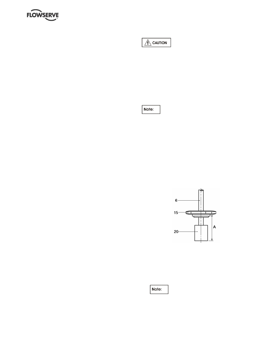
b) Position the first impeller on the shaft to
dimension 'A' as shown.
5WMV and 8WMV:
'A' = 77 mm (3.03 in.)
16WMV:
'A' = 91 mm (3.58 in.)
c) This dimension applies when the impeller nut is
tightened using a box spanner gripped in the
palm of the hand. Do not use a tommy bar or
other form of leverage at this stage. Check the
dimension and then tighten the impeller nut to the
recommended torque listed.
The final tightening will move the
impeller slightly.
d) If it has been removed, fit the stage piece adaptor
into the suction/discharge casing with three spots
of low strength Loctite, first ensuring that the
mating surfaces are clean.