1equipment check, Seal chamber requirements, 2mechanical seal installation – Flowserve U Series BW Seals User Manual
Page 2
1
Equipment Check
2
Seal Chamber Requirements
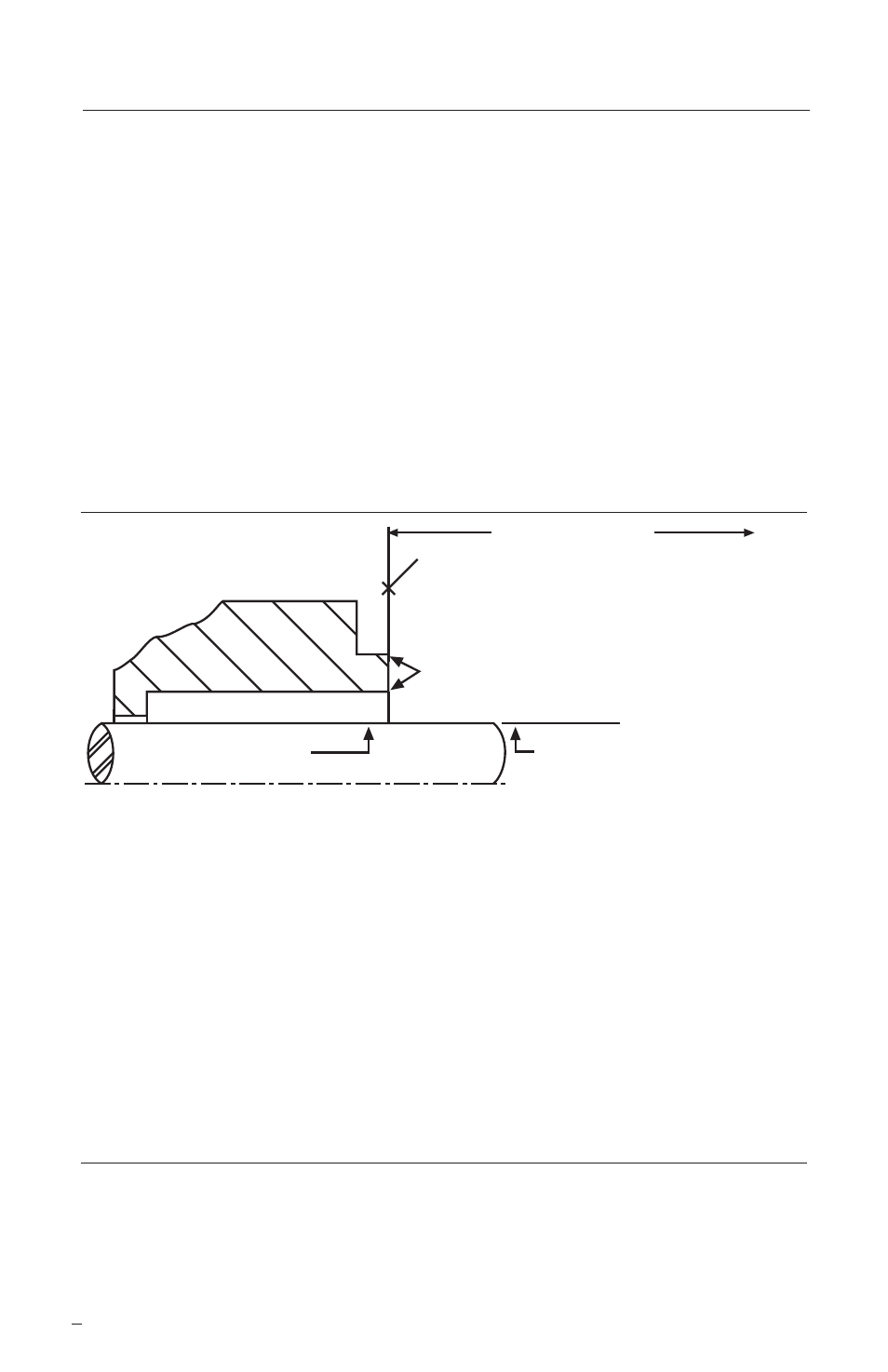
Figure 1
1.5
Check assembly drawing included with the seal for equipment dimensions,
seal design, materials of construction, and piping connections.
1.6
Measure all diameters and distances to ensure they are dimensionally the
same as shown on the seal assembly drawing.
1.7
Handle all seal parts with care, they are manufactured to precise tolerances.
The seal faces are of special importance and should be kept perfectly clean.
1.1
Follow plant safety regulations:
• lock out motor and valves.
• wear designated personal safety equipment.
• relieve any pressure in system.
• consult plant MSDS files for hazardous material regulations.
1.2
Adjust the bearings, coupling, and impeller so that the shaft is in its operating
axial position. Disassemble equipment to allow access to seal installation
area.
1.3
Remove all burrs and sharp edges from the shaft, sleeve, seal housing bore
and face, keyways, and any other feature that may contact sealing gaskets.
Replace worn components. Clean all piping plans.
1.4
Check requirements for shaft, sleeve, and seal housing. See Figure 1.
2
Mechanical Seal Installation
2.1
Review seal assembly drawing, seal assembly, and equipment prior to
installation. Read all notes on the seal assembly drawing. For hook sleeve designs,
confirm the seal setting length shown on the assembly drawing matches the
equipment. See Figure 1.
To first obstruction
Face of seal housing to be square to the
axis of the shaft to within 0.0005 mm/mm
(0.0005 inch/inch) of seal chamber bore TIR
and have a 1.6
μ
m (63
μ
inch) R finish or better
a
Gland pilot can be at either of these
register locations, concentric to within
0.125 mm (0.005 inch) of shaft or
sleeve OD TIR
Seal housing bore to have 3.2 μm
(125 μinch) R finish or better
Sleeve or shaft finish to be
0.8 μm (32 μinch) R or better
a
a
• Bearings must be in good condition
• Maximum lateral or axial movement of shaft (end play) = 0.25 mm (0.010 inch) TIR
• Maximum shaft runout at face of seal housing = 0.05 mm (0.002 inch) TIR
• Maximum dynamic shaft deflection at seal housing = 0.05 mm (0.002 inch) TIR
Shaft or sleeve OD
+0.000 mm (+0.000 inch)
-0.050 mm (-0.002 inch)
+0.000 mm (+0.000 inch) API 610/682
-0.025 mm (-0.001 inch) DIN/ISO
ANSI