Installed cartridge seal assembly, 3piping instructions – Flowserve U Series BW Seals User Manual
Page 3
2.3
Lightly lubricate external gaskets with a lubricant compatible with both handled
product and gasket material. Generally, silicon grease is suitable.
2.4
Install the seal onto the shaft and locate it against the face of the seal chamber.
If applicable, ensure the sleeve is aligned with drive features on the shaft.
2.5
Orient the ports on the seal gland(s) as indicated by the seal assembly drawing
and connected piping.
2.6
Evenly torque gland bolts/nuts for uniform gland pressure against the seal
chamber. On cartridge seals, do not yet tighten drive collar screws.
2.7
Complete the remaining equipment assembly including bearings, if applicable.
2.8
On cartridge seals, evenly tighten drive collar screws.
2.9
Disengage setting plates from the sleeve and secure in disengaged position.
2.10 Inspect equipment and driver alignment in accordance with coupling and/or
equipment manufacturer’s instructions.
2.11 After bringing the equipment up to operating conditions, recheck alignment
and make adjustments as necessary.
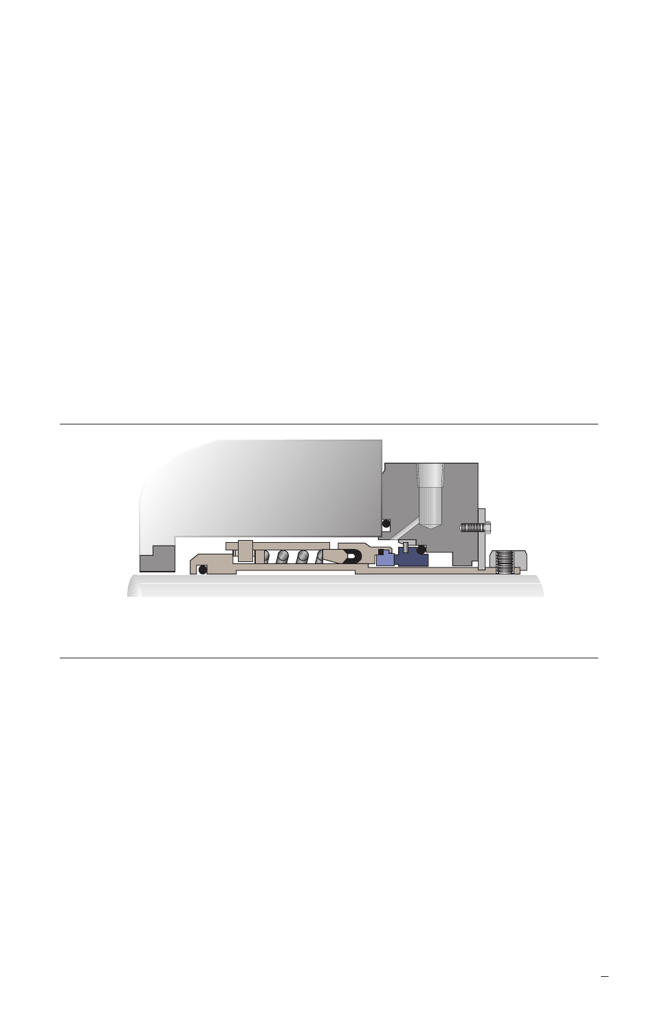
3
Installed Cartridge Seal Assembly
Figure 2
3
Piping Instructions
3.1
Refer to the seal assembly drawing for recommended seal piping plans.
If auxiliary systems are required, follow all installation and operating instructions
provided with these systems.
3.2
Minimize restrictions, total tubing length and number of bends especially in closed
loop systems. Unless otherwise specified, the minimum internal diameter for tubing
and connecting hardware should be 19 mm (0.750 inch).
3.3
Do not start the equipment dry. Vent the equipment, seal chamber, and all
piping systems then startup support systems before starting equipment.
The images of parts shown in these instructions may differ visually from the actual
parts due to manufacturing processes that do not affect the part function or quality.