6seal assembly instructions – Flowserve ISC2 Single metal bellows seal User Manual
Page 5
5
6
Seal Assembly Instructions
Some assembly steps include blind fits of pins and drive flats. Mark the locations
of the pins or drive flats with a felt tip marker, or align the feature with another
visible feature on the seal to assist with assembly. All seal faces should be
cleaned with ethyl alcohol prior to placing the faces together at each respective
step in the assembly process.
6.1 Arrange O-rings by diametrical size. There are two sizes: quantity 2 of the
largest size [13] and [76], and quantity 1 of the smallest size [19]. Prior to
installing each O-ring at its respective step, lightly lubricate with silicone
grease, unless an alternative lubricant is specified, and stretch slightly.
6.2 Place the sleeve assembly [1] on the work surface with the drive end (set
screw holes) positioned upward. For sizes ≤ 2.750 inch (70 mm), install the
vibration damper [183] into the back counterbore of the sleeve assembly.
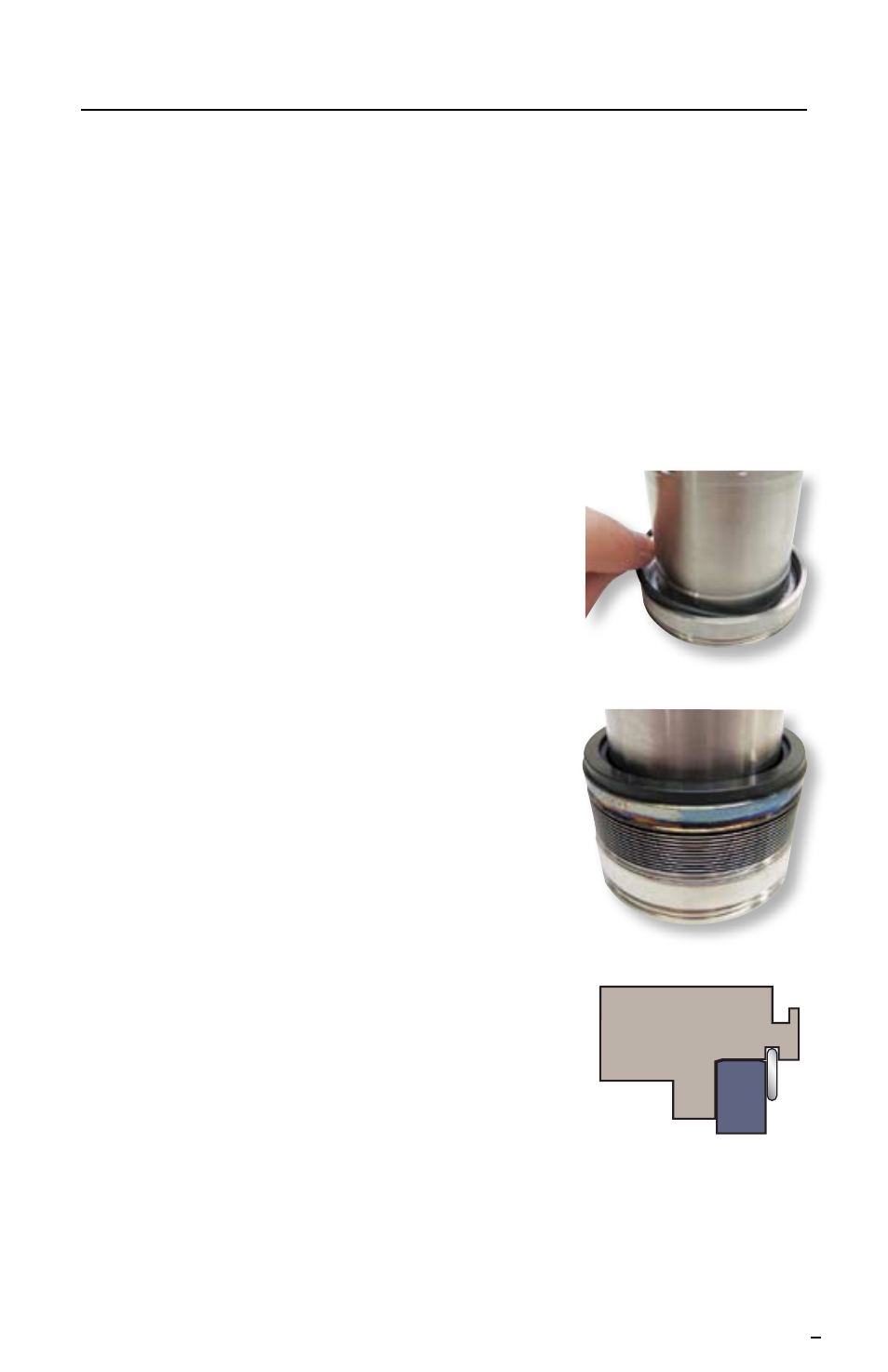
6.3 Select O-ring [19] and stretch slightly. Lightly
lubricate the O-ring using silicone grease.
For sizes
≤ 2.750 inch (70 mm) install the O-ring
into the sleeve assembly, on the inner diameter
groove of the sleeve. See Figure 7.
For sizes > 2.750 inch (70 mm)
install the O-ring
into the inner diameter groove of the bellows
assembly.
6.4 Select bellows assembly [79] and lightly lubricate
O-ring surface using silicone grease. Install the
bellows assembly [79] into the sleeve/O-ring
assembly. See Figure 8. Use hand pressure to
press the bellows assembly fully into place.
For sizes
≤ 2.750 inch (70 mm) ensure that the
flats on the bellows assembly and the flats on the
sleeve are aligned.
For sizes > 2.750 inch (70 mm) ensure
that the
drive slots on the bellows assembly and the drive
pins on the sleeve are aligned.
6.5 Clean the sealing face of the bellows assembly
[79] to remove any dirt, dust, fingerprints, grease
or any other residue using alcohol on a clean
cloth or tissue.
6.6 Select gland assembly [11] and use a parallel-
Figure 7
Figure 8
Figure 9
plate press to install the bushing [24] into the
outboard side of the gland. Once the bushing is fully pressed in the gland
assembly [11] (i.e. no gap behind bushing), insert the snap ring [111] into the
groove on the inner diameter of the gland to retain the bushing. See Figure 9.