Flowserve Airfin Coolers User Manual
Page 3
1.4
Select the proper location. It will be necessary to fabricate or purchase a
mounting bracket to suit your particular installation. See Figure 2 for
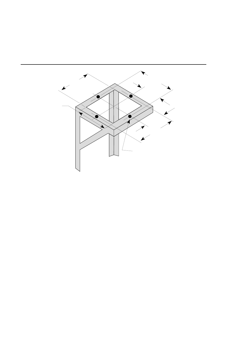
recommended mounting bracket dimensions. The Airfin Cooler should be
located 6-12” above and no more than 4’ from the seal chamber.
9.00" Min.
10.50"
9.00" Min.
5.25"
5.25"
10.50"
4 - .437” Dia. holes
as shown
Mounting Bracket Details
Figure 2
1.5
Carefully place the Airfin Cooler on the mounting bracket. The Airfin Cooler
should be positioned so that the least amount of elbows or tube bends are
needed for the inlet and outlet piping.
Note: If the inlet and outlet fittings are not in the desired positions, the coil
assembly can be rotated 360
°
to any desired position. Loosen the four hex
head bolts (Part No. 10 of Model 625 FC and Part No. 5 of Model 625 NC)
and rotate the cooling coil/shroud assembly to the desired position. Be sure
to tighten the four hex head bolts securely.
1.6
After the unit has been placed on the mounting bracket in the desired
position, secure it down with four hex nuts (3/8” - 16 UNC-2B) with lock
washers.
1.7
Consult your assembly drawing for the connections size and location. The
hot product line to the Airfin Cooler should be piped to the top of the unit
and the cooled product outlet line should be piped from the bottom of the
unit. Connect the inlet and outlet lines with suitable piping or tubing.
1.8
Be sure to install a vent value in the hot product inlet line. The vent valve
should be located at he highest point in the piping.
1.9
The Model 625 FC Airfin Cooler has a 1/3 HP motor. Consult the assembly
drawing for your motor specifications.
3