1nomenclature, Figure 1, Table 1 – Flowserve ISC2BB User Manual
Page 2
2
© Copyright 2000 Flowserve Corporation
1
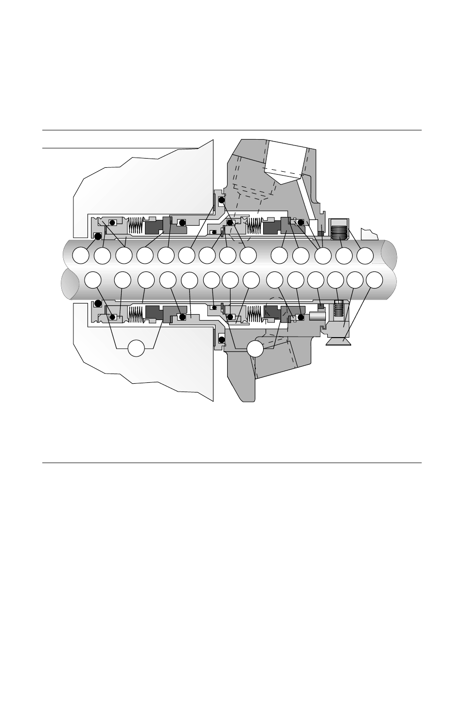
Nomenclature
Notes: - Inboard bellows assembly (34A) is interchangeable with outboard bellows assembly (34).
- Inboard mating ring (3C) is interchangeable with outboard mating ring (3B).
- Primary seal O-rings (P, P1, 6, 6A) are all the same size and cross section.
Figure 1
34
Outboard Bellows Assembly
34A
Inboard Bellows Assembly
3B
Outboard Mating Ring
3C
Inboard Mating Ring
P
Outboard Mating Ring O-ring
P1
Inboard Mating Ring O-ring
6
Outboard Bellows O-ring
6A
Inboard Bellows O-ring
G
Gasket
G1
Inner Gland O-ring
1
Gland Assembly
B
Carbon Bushing
1B
Gland Drive Ring
1C
Inner Gland
RR
Retaining Ring
Table 1
14
Rotor Carrier
CT
Centering Tab
K
Centering Tab Cap Screw
SL
Sleeve Assembly
10A
Drive Ring
M
Outboard Vibration Dampener
M1
Inboard Vibration Dampener
M2
Outboard Bellows Vibration Dampener
M3
Inboard Bellows Vibration Dampener
9
Sleeve Collar
13
Cup Point Set Screw
13A
Quarter Dog Set Screw
11
Sleeve O-ring
11A
Rotor Carrier O-ring
These instructions are written for trained, experienced technicians familiar with the basic
principles and tools involved in the installation, care and service of mechanical seals and seal
support systems. A complete reading of these instructions by personnel in contact with the
equipment is essential to safety. Incorrect installation, operation or maintenance can result in
personal injury or death to personnel and damage to the equipment.
6A
10A
10
P1
1C
11A
6
14
1B
P
13
9
1
M2
3B
G1
M
RR
G
M3
3C
SL
M1
11
13A CT
K
34A
34
B