Flowserve ISC2BB User Manual
Page 6
Advertising
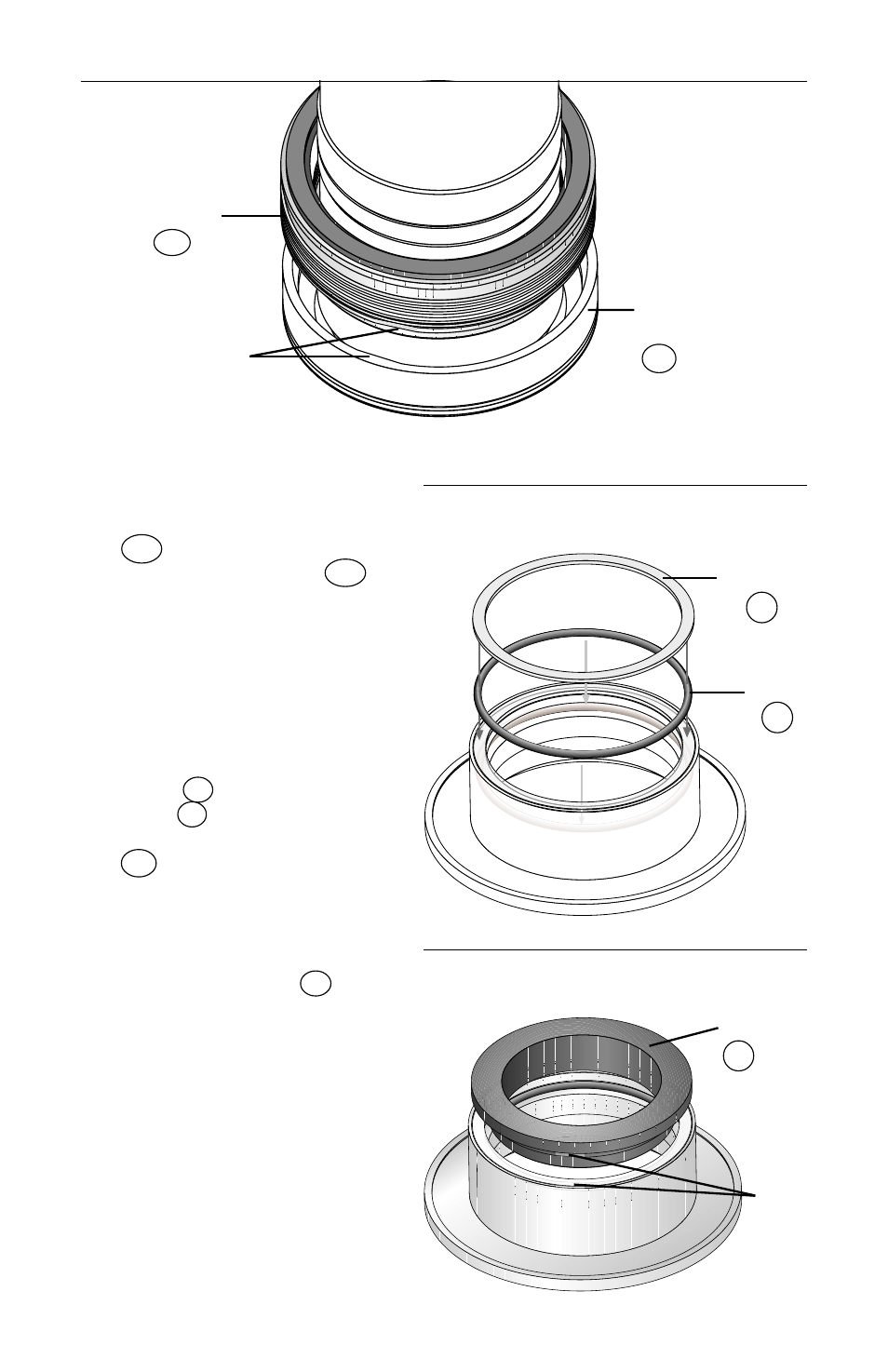
4.5 Align the two flats on the
inboard bellows assembly
34A
with the two flats on the
inside of the drive ring
10A
in the sleeve end housing,
and press the bellows
assembly into place using
finger pressure only.
(
Figure 8
)
4.6 Place the inboard mating ring
O-ring
P1
into the inner
gland
1C
. Place the inboard
bellows vibration dampener
M3
into the inner gland.
(
Figure 9
)
4.7 Align the two flats on the
inboard mating ring
3C
with the two flats on the
inside of the inner gland, and
press the mating ring in place
using finger pressure only.
(
Figure 10
)
6
Figure 9
Figure 8
34A
Inboard
Bellows
Assembly
Drive Flats
10A
Drive
Ring
O-ring
P1
Vibration
Dampener
M3
Figure 10
3C
Mating
Ring
Drive
Flats
Advertising
See also other documents in the category Flowserve Hardware:
- Tandem Seal (8 pages)
- 978 Chemiepac (12 pages)
- ISC2 Single Pusher Repair (8 pages)
- LS-300 Series Durametallic (4 pages)
- Pac-Seal Type 16 (8 pages)
- U Series BW Seals (4 pages)
- ISC2 Dual Pusher Repair (12 pages)
- ISC2 Single metal bellows seal (8 pages)
- Durametallic Double CRO (8 pages)
- VRA-C Series Durametallic (4 pages)
- ISC2 Dual metal bellows sea (12 pages)
- Single Inside Pusher Type Seal (8 pages)
- Bearing Gard (2 pages)
- X-200 (12 pages)
- GTS Series (12 pages)
- MSS Series (12 pages)
- SLC Series Interseal (12 pages)
- QB Series BW Seals (8 pages)
- SLM-6100 (12 pages)
- SLM-6200 (12 pages)
- High Temperature Metal Bellows Seals (8 pages)
- X Series BW Seals (8 pages)
- ML-200 Series Durametallic (8 pages)
- ML-200 Series Durametallic (8 pages)
- Circulator (12 pages)
- ISC Series (16 pages)
- Gas Barrier Control System (4 pages)
- CPM Series (8 pages)
- CPM Series (12 pages)
- Mechanical Seal and Seal Support System Storage (4 pages)
- RIS Seal (12 pages)
- 682 Seal Cooler (8 pages)
- ISC2 Series (8 pages)
- ISC2 Series (116 pages)
- Pac-Seal Type 52 (8 pages)
- Pac-Seal Type 31 (8 pages)
- ST Series (8 pages)
- Mechanical Seal General (16 pages)
- Dual Pressurized Seals (8 pages)
- Uniseal Series BW Seals (8 pages)
- XLC Series (8 pages)
- PSS II Durametallic (8 pages)
- PSS II (16 pages)
- ISC1SX (8 pages)
- ISC1PX (8 pages)