4seal assembly instructions – Flowserve ISC2PP User Manual
Page 5
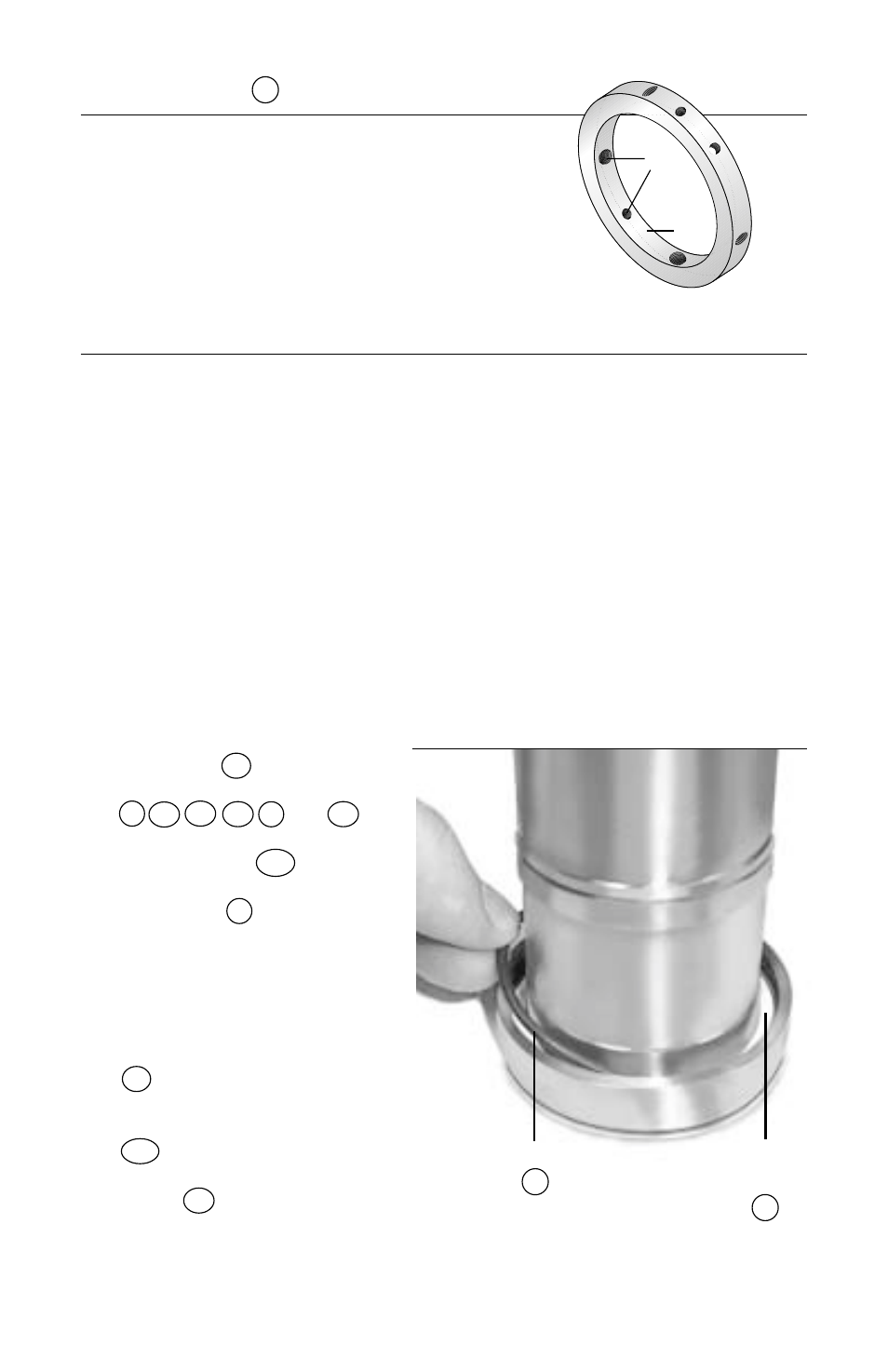
4.4 Place the sleeve assembly
SL
on a flat surface with the
collar end facing up. Install
the inboard vibration dampener
M1
into the sleeve end housing.
Place the inboard mating ring
O-ring
6A
in the sleeve O-ring
groove behind the surface with
drive flats in the sleeve. (
Figure 7
)
5
4
Seal Assembly Instructions
4.1 Tools Required
•
3
/
32
",
1
/
8
" hex key wrenches (Sizes < 2.625");
1
/
8
",
3
/
16
" hex key
wrenches (Sizes 2.625" and larger)
• Silicone grease (included in repair kit)
• Ethyl alcohol or acetone and clean, lint free towel for cleaning seal faces
4.2 As part of the assembly of the seal, there are several blind fits of pins and
drive flats. It may be helpful to mark the locations of the pins or drive flats
with a felt tip marker, or to align the feature with another visible feature on
the seal to assist with assembly. All seal faces should be cleaned with
alcohol or acetone prior to placing the faces together at each respective step
in the assembly process.
4.3 Arrange O-rings by diametri-
cal size. There are four sizes
total: quantity 1 of the largest
size O-ring
G1
, quantity six
of the 2
nd
largest size O-rings
P
P1
P2
P3
6
and
6A
,
quantity one of the 2
nd
small-
est size O-ring
11A
and
quantity 1 of the smallest
size O-ring
11
. Prior to
installing each O-ring at its
respective step, lightly
lubricate with silicone grease
and stretch slightly.
3.6 Sleeve Collar
9
(
Figure 6
)
A
Threaded holes - Inspect for thread
damage and re-tap as necessary.
B
ID bore roundness -
no greater than
0.002" TIR
C
Set screws - Replace cup point and dog point set
screws with those included with the repair kit.
Make sure the same threaded holes are used with
the same type set screws.
Figure 6
B
A
M
Vibration
Dampener
O-ring
6
Figure 7