Flowserve ISC2PP User Manual
Page 7
Advertising
7
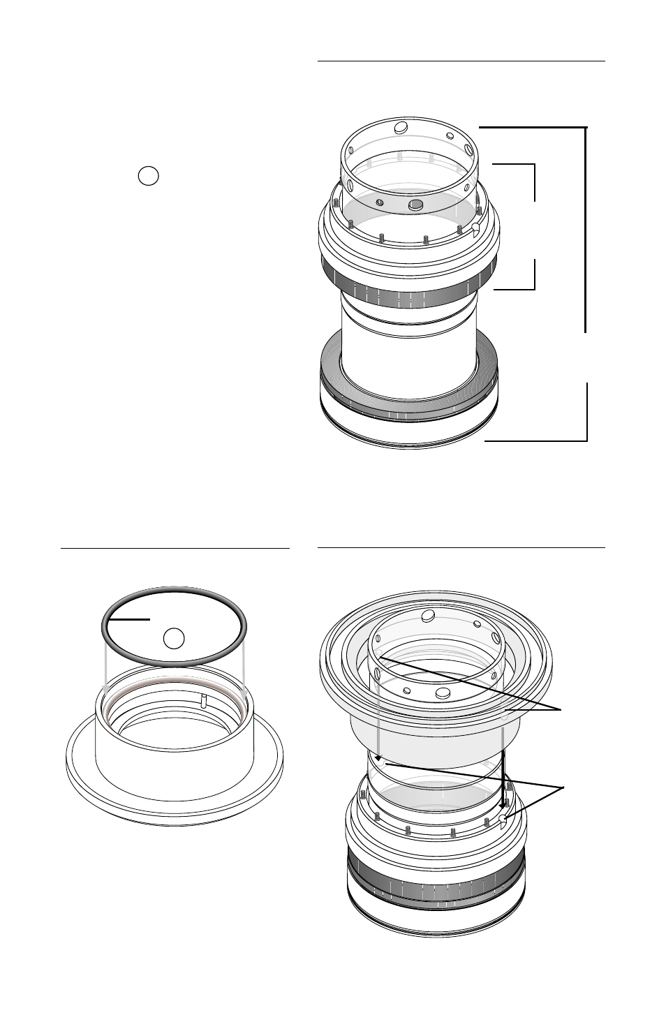
4.9 Place the stator and stator
carrier assembly face down
onto the sleeve/mating ring
assembly. (
Figure 11
)
4.10 Place the inboard dynamic
O-ring
P1
in the dynamic
O-ring surface of the inner
gland. (
Figure 12
) Align the
inner gland drive pins with
the slots in the outside diam-
eter of the stator carrier and
press the inner gland onto
the stator carrier, using even
hand pressure. (
Figure 13
)
Caution: do not rotate the
inner gland to align the pins
while pressing down. This
could damage the springs.
Once the inner gland is in the
proper position, do not rotate
it until the seal is fully assem-
bled to ensure that the pins
remain aligned.
Figure 11
Figure 12
Figure 13
Slots
Drive
Pins
P1
O-Ring
Stator
Carrier
Assembly
Sleeve/Mating
Ring Assembly
Advertising