2seb installation, 3operational recommendations, Typical seal gard – Flowserve SEB User Manual
Page 3: Figure 2, Figure 3
3
2
SEB Installation
2.1
No tools are required for installation.
2.2
Lightly lubricate O-ring G
2.3
Remove warning tape from OD of the SEB
Note: After the warning tape has been removed, the SEB can be separated into two halves.
Care must be taken when handling the SEB after removing this tape, in order to
assure the individual halves do not separate unintentionally.
SEB
Figure 2
2.4
Align each individual half of the SEB
around the shaft by engagement of the
alignment pins.
2.5
While compressing the OD of the SEB
gently slide the assembly into the seal
chamber bore and fully seat the SEB against
the throat restriction. See Figure 2. Note the
SEB can be installed in either direction
inside its target seal chamber.
Caution: Not fully seating the SEB against
the throat restriction may result in
SEB contact with the mechanical
seal rotating components,
therefore, resulting in damage and
performance degradation of the
SEB or the mechanical seal.
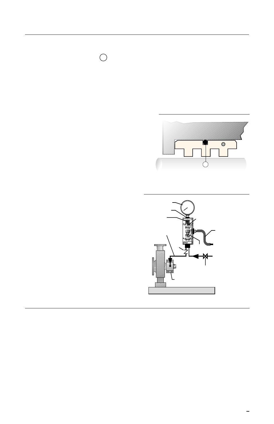
2.6
Complete the seal installation and
equipment assembly. The SEB
performance is enhanced with a clean
fluid flush. The recommended flush
should be from a clean external source
(Plan 32). Connect the flush line and
follow operational recommendations.
See Figure 3.
3
Operational Recommendations
3.1
Do not exceed corrosion limits. The SEB is designed to resist corrosion by most
chemicals. However, do not expose the SEB materials of construction to products
outside of their corrosion limits. Consult your Flowserve Representative for chemical
resistance recommendations.
3.2
Do not exceed the recommended temperature limits of 32
°
to 250
°
F (0 to 121
°
C).
3.3
Do not exceed the speed limits of 10 to 80 fps (3-25 m/s).
3.4
Seal chamber should be flooded and properly vented prior to pump start up.
For special problems encountered during installation, contact your nearest Flowserve Sales
and Service Representative or Authorized Distributor.
Supply of Clean
Flush
Single Flowserve Seal
Durametallic
®
4
10
20
GPH H
2
O
100
PSI/kPa
50
Seal Gard
™
I
LPM H
2
O
15
30
To gland flush tap,
flush mixes with
pumped fluid
Pressure gauge
Clean-out port
Supply flow
control valve
Flow tube
Float
Flow Reading
Check
valve
On/off supply valve
Alarm probe
option
Flow Solutions Division
Typical Seal Gard
Figure 3
G