Description, Seal chamber requirements, 1equipment check – Flowserve SEB User Manual
Page 2: Figure 1
2
© Copyright 2005 Flowserve Corporation
Description
The Solids Excluder Bushing (SEB) is an engineered device specifically designed to extend
the mean time between failure (MTBF) of a mechanical seal. Pumps that operate with
standard bore seal chambers (packing boxes) tend to accumulate solids from the pumpage in
the seal chamber. Over time, the accumulated solids in the seal chamber can cause
component clogging, erosive or abrasive wear, and seal face overheating. Seal chambers are
commonly flushed with an external clean fluid to help reduce seal damage, however flush
rates come at the expense of additional resources and maintenance. When an SEB is
installed in the throat of a seal chamber, it transfers solids from the seal chamber to the
pumpage, leaving behind a clean environment for the mechanical seal. Removing solids from
the seal chamber reduces seal component erosion, shaft sleeve wear, and seal hang-up
resulting in greater reliability of the mechanical seal.
Seal Chamber Requirements
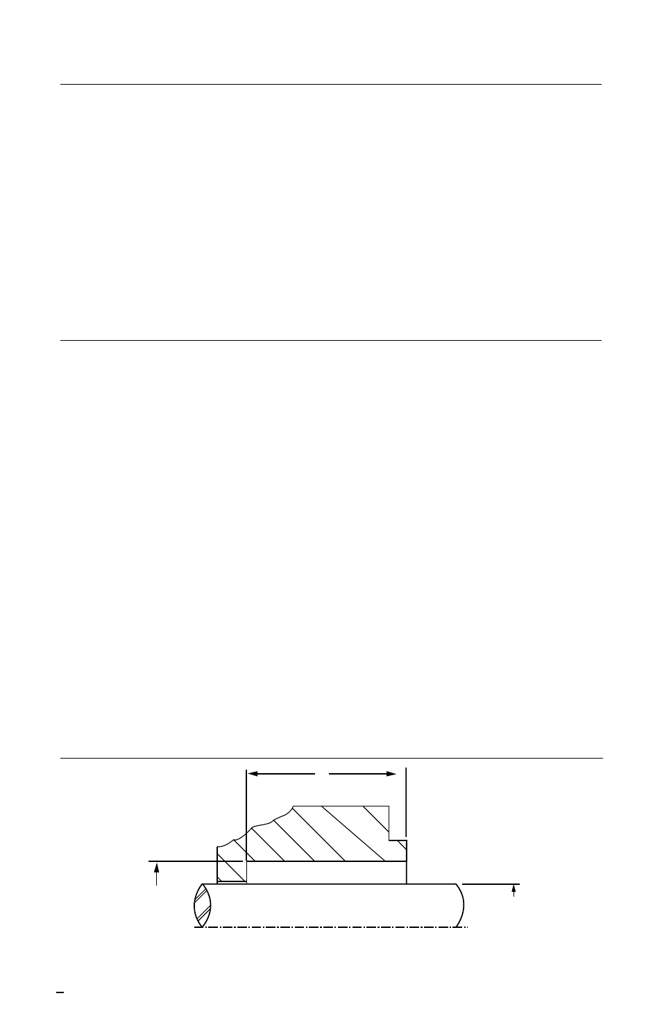
Figure 1
C
Shaft or sleeve OD to
be
±
0.001 inch (0.03mm) of
nominal and runout with
0.005 inch (0.13mm) FIM
• Shaft Rotation viewed from mechanical seal end.
• Bearings must be in good condition.
• Maximum dynamic shaft deflection at SEB
0.010 inch (0.25mm) FIM
Minimum Depth of Chamber = 0.5 inch
(12.7mm) plus seal extension into seal
chamber plus length of SEB
B
A
Seal housing
±
0.005 inch
(0.13mm) of nominal bore,
have a
√
125
µ
inch (3.2
µ
m)
R
a
finish or better and be
concentric to shaft within
0.005 inch (0.13mm) FIM
Note: The equipment shaft
rotation direction is critical to
the performance of the SEB and
should be confirmed prior to
installation
Installation according to the following steps will assure long trouble free life of the SEB.
1
Equipment Check
1.1
Follow plant safety regulations prior to equipment disassembly:
•
lock out motor and valves.
•
wear designated personal safety equipment.
•
relieve any pressure in the system.
•
consult plant Material Safety Data Sheet (MSDS) files for hazardous material
regulations.
1.2
Disassemble equipment in accordance with equipment manufacturer’s instructions to
allow access to seal installation area.
1.3
Remove existing mechanical seal and bushing or compression packing and
packing gland.
1.4
Make sure the bore of the seal housing is clean and free of burrs, cuts, dents, or
corrosion that might inhibit proper seating of the SEB at the throat of the seal housing.
1.5
Check equipment dimensions and Shaft Rotation. They must agree with the
dimensions shown in Figure 1 and the assembly drawing supplied with the SEB. Critical
dimensions include the shaft OD (A), the seal chamber bore (B) and the chamber
depth (C).
1.6
Handle SEB with care, it is manufactured to precise tolerances.