1 equipment check and seal preparation – Flowserve Circpac MD User Manual
Page 2
1 Equipment Check and Seal Preparation
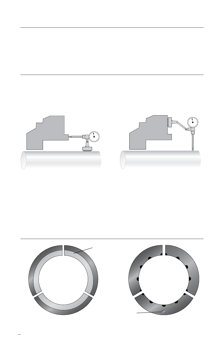
1.1 Refer to Figure 1 for sleeve/shaft and equipment requirements.
1.2 The equipment sleeve/shaft must be clean and free of any burrs, nicks or scratches.
1.3 Check seal assembly drawing for specific equipment requirements, reference
dimensions, special instructions, piping connections, and materials of construction.
2
1.4 Segmented rings have matched joints and must be mated together per the segment
numbering scheme shown in Figure 2 for 3 segment rings. During assembly, keep all
numbers facing the same direction. The polished side is a sealing surface and should
be handled carefully.
Note: Do not use grease or other lubricants on segmented carbon rings, housing,
or shaft.
1.5 Use caution when handling heavy gland ring halves. Maneuver and support large
parts carefully to avoid personal injury and/or damage to segmented rings.
Seal chamber squareness to the shaft
centerline should be within 0.25 mm per
25 mm shaft diameter (0.010” per 1” shaft
diameter). Seal chamber face surface
finish should be 125 RMS or better.
Shaft runout should not exceed 0.10 mm
(0.004”) FIM. Shaft surface finish should
be 16 RMS or better.
Figure 1
Figure 2
Polished Face
Drive Pin
2
2
2
Back
Front