2 seal installation (split housing designs) – Flowserve Circpac MD User Manual
Page 3
3
2 Seal Installation (Split Housing Designs)
Seal components are assembled in the following order: housing gasket (if separate),
bottom housing half, segmented rings, and upper housing half. Housing gasketing, housing
weight support, centering methods, and multiple ring sequencing should be considered
prior to starting.
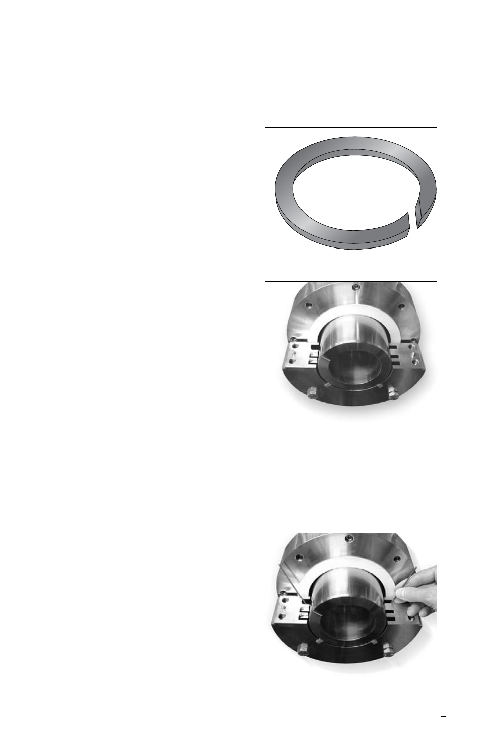
2.1 The housing gasket may be supplied split
and bonded to the housing halves or as a
solid ring, depending on gasket type. If the
gasket is already bonded to the housing
halves, no extra preparation is necessary.
Otherwise, with a sharp cutting instrument,
carefully cut the gasket tangential to the
gasket ID with a 45° bias in the thickness, as
shown in Figure 3. At the cut joint, bend the
gasket to fit around the shaft. Position the
gasket near the equipment face.
2.2 The housing half with drive pin slots at the
joint surface is the bottom half of the housing
ring and is installed first. Orient the lower
housing half toward the equipment in the
direction indicated on the seal assembly
drawing or marked on the housing. Support
the lower half of the housing on the
equipment with loosely engaged bolts or
studs such that the gasket area is accessible
and the segmented ring grooves are fully
exposed.
2.3 If the seal is designed with multiple
segmented rings, start at the housing end
that will be obstructed by additional rings.
Complete each ring before starting the next.
2.4 Feed the garter spring into the ring groove
in the lower housing half. Leave an equal
amount of spring hanging out on each side.
Figure 3
Figure 4
Figure 5