1 equipment check, Seal chamber requirements, Figure 1 – Flowserve CBR Series User Manual
Page 2
2
1 Equipment Check
1.1
Follow plant safety regulations prior to equipment disassembly:
• lock out motor and valves.
• wear designated personal safety equipment.
• relieve any pressure in system.
• consult plant MSDS files for hazardous material regulations.
1.2
Disassemble equipment to allow access to seal installation area.
1.3
Remove all burrs and sharp edges from the shaft or sleeve includ-
ing sharp edges of keyways and threads. Replace worn shaft or
sleeve. Make sure the seal housing bore and face are clean and
free of burrs.
1.4
Check requirements for shaft, sleeve and seal housing.
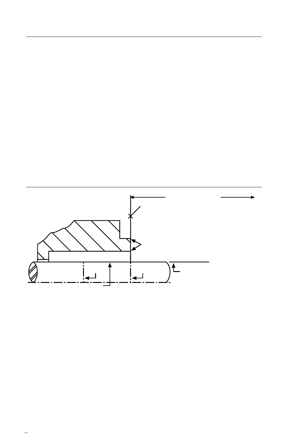
See Figure 1.
To first obstruction
Face of seal housing to be square to the axis
of the shaft to within 0.0005 inches per inch of
seal chamber bore (0.013 mm) FIM and have a
√63 µinch (1.6 µm) R finish or better
a
Gland pilot can be at either of these
register locations. concentric to within
0.005 inch (0.13 mm) FIM of shaft or sleeve OD
Sleeve or shaft finish to be
32
µinch (0.8 µm) R or better
a
a
Scribe
Mark A
Shaft or sleeve OD
+0.000 inch (+0.000 mm)
-0.002 inch (-0.050 mm) ANSI
+0.000 inch (+0.000 mm) API 610
-0.001 inch (-0.025 mm) DIN/ISO
• Bearings must be in good condition
• Maximum lateral or axial movement of shaft (end play) = 0.010 inch (0.25 mm) FIM
• Maximum shaft runout at face of seal housing = 0.002 inch (0.05 mm) FIM
• Maximum dynamic shaft deflection at seal housing = 0.002 inch (0.05 mm) FIM
Scribe
Mark B
Seal housing bore to have
√125 µinch
(3.2
µm) R finish or better
Seal Chamber Requirements
Figure 1
1.5
Check assembly drawing included with the seal for specific
seal design, materials of construction, dimensions, and piping
connections.
1.6
Check shaft or sleeve OD, box bore, box depth, and distance
to first obstruction to ensure that they are dimensionally the same
as shown on the seal assembly drawing.