2 installation, Basic cbr – Flowserve CBR Series User Manual
Page 3
3
1.7
Check gland pilot and bolt holes to ensure they are adaptable
to the equipment and are the same as shown on the assembly
drawing.
1.8
Handle all seal parts with care, they are manufactured to precise
tolerances. The seal faces; Seal Ring and Insert, are of special
importance. These two sealing faces are lapped flat to within
three light bands (34.8 millionths of an inch).
Keep the seal faces
perfectly clean at all times.
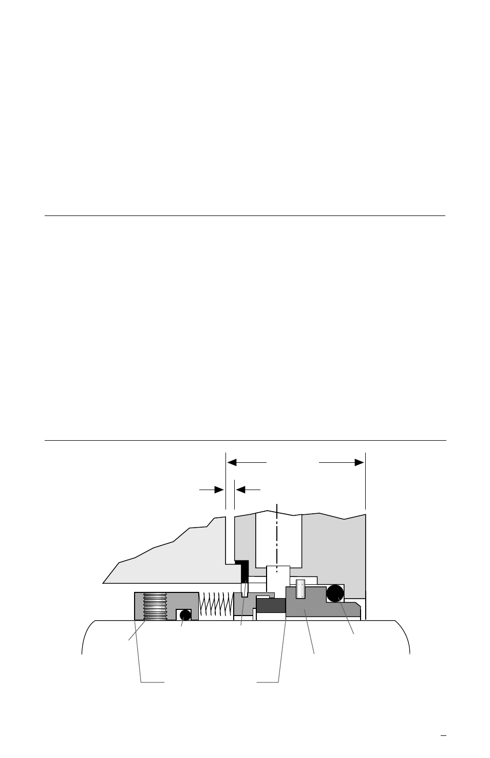
2 Installation
The basic CBR design is shown in Figure 2. Variations may include
rotating face gasket, seat gasket, and environmental control features.
See the Flowserve assembly drawing included with each complete seal
for details. Additional recommendations for vetical pumps are shown in
section 3.
2.1 Scribe mark
A, Figure 1, on the shaft or sleeve to line up with the
face of the seal housing. The shaft or sleeve must be in its final
axial operating position with regard to the seal housing face before
mark
A is scribed.
Basic CBR
Figure 2
1.19
0.06
Set
Screw
Bellows
Adapter
Gasket
Gasket
Stationary
Face
Seat
Gasket
Gland
Bellows
Assembly