General infor mation – Flowserve V-376 R4 Edward Valves User Manual
Page 10
11
Flow Control Division
Edward V
alves
W
ARNING
Edward valves are not provided with a pres-
sure relief device. A pressure relief device
must be provided elsewhere in the piping
system to prevent the piping system pressure
from exceeding the maximum rated pressure
of the valve.
PIPING SUPPOR
T
Piping should be suppor
ted sufficiently to
preclude excessive end loads on the valve.
VA
LVE INST
ALLA
TION GUIDELINES
Except as noted below
, Edward stop valves
and stop-check or check valves with springs
can be installed in any position. Installed
positions with the valve cover or bonnet
below horizontal, where dir
t and scale can
accumulate in the valve neck, should be
avoided.
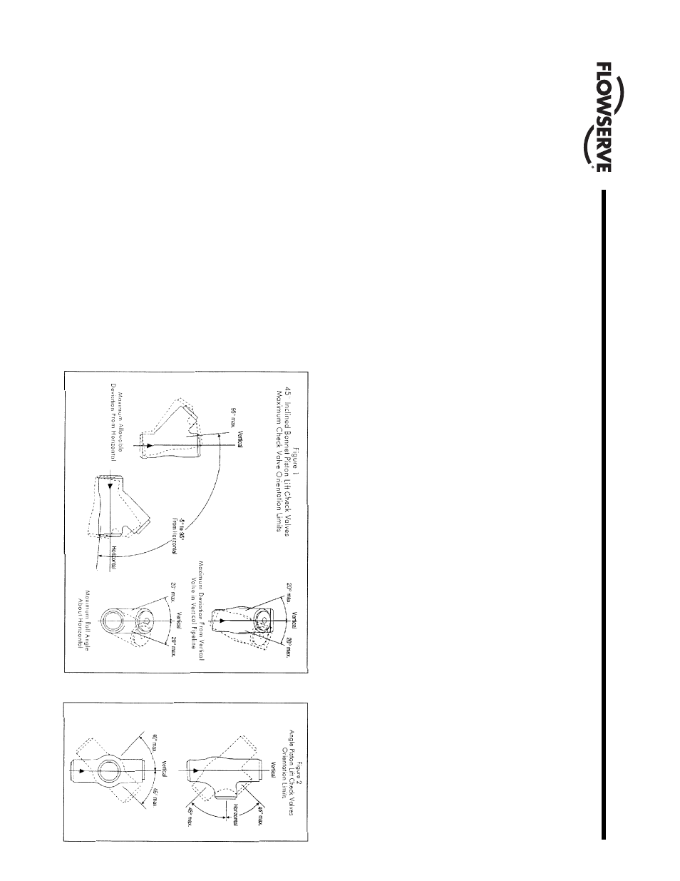
For optimum per
for
mance, the orientation
limits shown in Figures 1 and 2 should
be obser
ved even for spring-loaded
check valves.
The orientation limits shown in Figures 1
and 2 must not be exceeded for Edward
stop-check valves and check valves with-
out springs. The limitations given for line
inclination and bonnet roll angle should
not be combined.
All check and stop-check valves should be
installed with 10 or more diameters
of straight pipe upstream of the valve
to minimize flow disturbances. For addi-
tional infor
mation, refer to the “T
echnical”
section of the Edward V
alves Catalog,
Publication No. EV
-100.
SEA
T AND DISK JOINT LEAKS
A leak existing between the seat and disk of
a closed valve might be indicated by one of
the following: a definite pressure loss in the
high-pressure side of the valve; continued
flow through an inspection drain on the low-
pressure side; or
, in hot water or steam lines,
a downstream pipe that remains hot beyond
the usual length of time and conductivity
range.
Such a leak may be the result of closing on
dir
t, scale or other foreign matter in the line.
It may also develop because of the operator’
s
failure to close the valve tightly
. An increased
velocity is impar
ted to a flow forced through
a ver
y small opening. This increased velocity
subsequently gives rise to the “cutting” of
both disk and seat, par
ticularly by par
ticles
of line scale or rust in suspension or nor
mal
solids in solution. In spite of the fact that the
hard-sur
faced material on the seat and disk is
corrosion- and erosion-resistant, grooves, pit
marks, or other sur
face irregularities may be
for
med on the seat and disk joint sur
faces
when the disk is closed against a foreign
body on the seat. This sometimes occurs dur-
ing the initial star
t-up of a piping system.
Leakage of steam through a valve that is
badly steam-cut has a whistling or sonorous
sound. If the valve is only slightly steam-cut,
however
, leakage is identified by subdued
gurgling or weak popping sounds. These
sounds can be heard through a stethoscope
or by placing one end of a stick against the
valve body while holding the other end
between the teeth, with hands over the ears.
General Infor
mation
11