Flowserve Valtek Beta Positioners for Control Valves User Manual
Page 4
24-4
Flowserve Corporation, Valtek Control Products, Tel. USA 801 489 8611
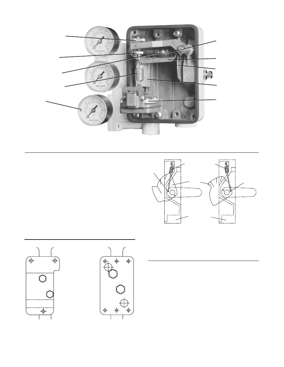
Hole A
L-R
L-D
Air-to-Open Air-to-Close
(Air-to-Retract) (Air-to-Extend)
Figure 6: Return Spring / Cam Mounting
(viewed from positioner’s right side)
Positioner
Base
Return Spring
Hole B
Cam
Installation
The installation section of this bulletin details how to
install the positioner on linear and rotary actuators.
Reversing the air action on linear and rotary actuators is
also covered along with an explanation of how to con-
vert the positioner from an I/P to pneumatic or pneu-
matic to I/P control signal.
Installing Positioner on Linear Actuators
Information for installing or retrofitting the Beta Posi-
tioner on all sizes of linear actuators follows:
Figure 4: Beta Positioner with Pneumatic Module
Zero Adjustment
Knob
Zero Adjustment
Locking Knob
Range Adjustment
Locking Screw
Feedback Spring
Pneumatic
Module
Range Adjustment
Gear
Range Arm
Cam
Spool Valve
Instrument Signal
Capsule
NOTE: When retrofitting the Beta Positioner to an
actuator equipped with a Moore or comparable posi-
tioner, remove the existing positioner, bracket, stem
clamp, and associated bolting. If retrofitting to an actua-
tor equipped with a Valtek Beta pneumatic, system 80,
or XL positioner, the same bracket, stem clamp, and
bolting can be used.
1. Place the new stem clamp (if applicable) onto the
actuator stem with the boss on the right side as
illustrated in Figure 3.
2. Mount the positioner bracket to the yoke leg which
has the stroke indicator plate attached to it and in
the correct position as shown in Figure 5.
Size 25, 100, 200 Size 50
Figure 5: Mounting Bracket