Flowserve Valtek Beta Positioners for Control Valves User Manual
Page 8
24-8
Flowserve Corporation, Valtek Control Products, Tel. USA 801 489 8611
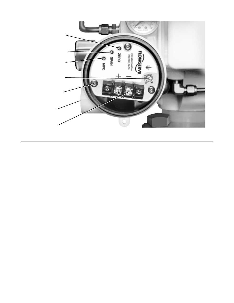
Zero Adjusting Pot
Span Adjusting Pot
Minimum Pressure
Cutoff
Grounding Screw
Circuit Board
Mounting Screws
Electrical Port
Terminal Block
Adjusting Minimum Pressure Cutoff;
I/P Module Pressure Regulator or Module
Output; Calibrating and Adjusting the NT
3000 I/P
Refer to Installation, Operation, Maintenance Instruc-
tions 47, NT 3000 Series Electro-pneumatic Transducer
Module, for instructions on adjusting the MPC feature,
adjusting the I/P module pressure regulator output,
adjusting I/P module pressure modulator or calibration
of the I/P module zero and span settings.
MAINTENANCE
Beta Positioner Maintenance
General maintenance procedures for the Beta posi-
tioner on both rotary and linear actuators are the same.
At least once every six months, check positioner for
proper operation by following the steps outlined below.
1. Maintain a clean air supply, free of dust, oil, and
water. It is recommended that an air filter be used to
ensure a clean air supply to positioner. Check and
maintain air filter at least every six months.
NOTE: The air supply should conform to ISA
Standard S7.3 (a dew point at least 18
O
F below
ambient temperature, particle size below 5 microns,
oil content not to exceed 1 part per million).
2. Make sure all arms and levers move freely.
3. Check for and tighten any loose parts.
4. Be sure there are no leaks in the air supply.
5. Check and maintain the coalescing filter element in
the I/P module every six months.
6. Refer to the “Troubleshooting” section of this bulle-
tin in case of problems.
Removal and Repair of Pilot Valve
To remove or repair the positioner pilot valve, refer to
Figure 17 and proceed as follows.
1. Loosen the zero adjustment locking knob (23) and
zero adjusting knob (20). Disconnect the feedback
spring (34) from the zero adjusting screw (24).
Remove the feedback spring (34) from the posi-
tioner assembly. Rotate the zero arm (22) out of the
way before removing the snap ring (8) holding the
range adjustment arm (13) to the base (7). Remove
the range adjustment arm (13).
2. Remove the two screws (53) holding the pilot valve
assembly (40, 52) to the base (7). Remove the pilot
valve assembly (40, 52) from the positioner, being
careful not to damage the spool valve or summing
beam assembly (41). Slide the spool (40) from the
spool valve body (52) and check it for dirt build-up
Figure 10: I/P Module Circuit Board
(housing cover removed)