Unpacking, Installation, Quick-check – Flowserve Valtek Tek-Check User Manual
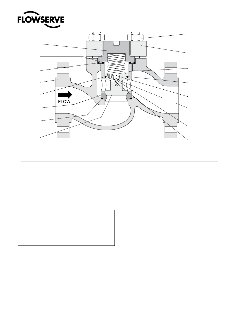
Page 2: Figure 1: non-slam piston check valve
2
®
User Instructions Tek-Check Valve - VLENIM0019-05 06/09
GENERAL INSTRUCTIONS
Valtek
®
Tek-Check is a high performance piston check valve featuring
piston and non-slam piston designs. Many features have been incor-
porated into the design to maintain maximum interchangeability with
other Flowserve
TM
valves.
The following instructions are designed to assist in unpacking, installing and
performing maintenance as required on Tek-Check valves. Product users and
maintenance personnel should thoroughly review this bulletin prior to performing
any maintenance on the valve.
To avoid possible injury to personnel or damage to valve
parts, WARNING and CAUTION notes must be strictly
adhered to. Modifying this product, substituting non-
factory parts, or inferior parts, or using maintenance
procedures other than outlined could drastically af-
fect performance and be hazardous to personnel and
equipment.
Unpacking
1. While unpacking the valve, check the packing list against materials
received. Lists describing valve and accessories are in each shipping
container.
2. When lifting the valve from the shipping container, attach straps to
lifting lugs, if provided, or position straps around the valve body,
behind the end flanges.
3. Contact your shipper immediately if there is shipping damage.
4. Should any problem arise, call your representative.
Installation
1. Before installing the valve, clean the line of dirt, scale, welding
chips, and other foreign material.
2. Valtek Tek-Check valves are designed to open with as little as
five psi (35 kPa) pressure difference across the valve.
3. Double-check flow direction to be sure the valve is installed
correctly. Flow direction is shown by the arrow attached to the
bonnet flange. If flow arrow is not attached, refer to Figure 1 or
2 for proper flow direction (flow direction is always under the
plug).
CAUTION: Valve will not operate if installed incorrectly.
Quick-check
After the valve is installed in the line, check for correct operation as
follows:
1. Pressurize the line, both upstream and downstream of the valve.
2. Drain off the upstream pressure until the valve closes. Most
valves mounted in a horizontal pipeline should close when the
upstream pressure is one psi (7 kPa) less than the downstream
pressure.
3. Increasing the upstream pressure to five psi (35 kPa) more than
the downstream pressure should open the valve.
4. When the valve is closed, check for noticeable leakage. If leakage
exists, refer to ‘Troubleshooting’ section.
Figure 1: Non-slam Piston Check Valve
NOTE: Item numbers correspond directly to valve‘s bill of material. Refer to it for specific part numbers.
Bonnet
(Item No. 40)
Retainer Gasket
(Item No. 56)
Bonnet Gasket
(Item No. 58)
Body
(Item No. 1)
Orifice
(Item No. 130)
Seat Ring
(Item No. 20)
Seat Ring
Gasket
(Item No. 55
)
Piston
(Item No. 50)
Bonnet Flange
Bolting
(Item No. 108/111/114)
Bonnet Flange
(Item No. 70)
Retainer
(Item No. 30)
Piston Seal
(Item No. 65)
Plug Check Seat
(Item No. 131)
Plug Check Seat
Gasket
(Item No. 62)
Ball
(Item No. 132)
Spring
(Item No. 135)
(upstream)
(downstream)