Flowserve B18 Series Multi-way Valve User Manual
User instructions
3
HEALTH AND SAFETY
When installing or maintaining valves:
a)
Conduct a risk assessment and eliminate or reduce hazards to an acceptable level.
b)
Work in accordance with Safe Systems of Work.
c)
Observe all site Health and Safety Rules in particular Permit to Work and Hot Work procedures.
d)
Wear all necessary Personal Protective Equipment.
e)
Never remove or maintain a valve or joint unless the line has been fully de-pressurised, drained and where
necessary, purged of toxic / explosive / flammable media. Always operate the valve to the open position to
ensure that no trapped pressure exists within the cavity.
f)
Never handle valves that have been used on harmful substances unless they have been completely
decontaminated and certified safe to handle.
g)
Never use a valve on a duty which exceeds its prescribed operating parameters. Refer to Flowserve Flow
Control (UK) Ltd Technical Sales for performance curves or further information.
h)
Never modify or alter valves unless the manufacturer has been consulted or recommends such changes.
i)
The valves wrenches are only designed for use in operating the valves and must not be used to carry them
by. Failure to observe this warning may result in operator injury.
j)
Due to the large physical size and weight of some sizes of this product, always use correct lifting methods
and equipment when installing, removing and maintaining the product, and that it is correctly supported in its
final operating location.
k)
Due to the variety of duties on which this product can be employed, it is the end users responsibility to
ensure the compatibility of the media with the materials of construction of the product for each specific appli
cation (i.e.corrosion and erosion which may affect the integrity of the pressure-containing envelope).
l)
Before equipment is installed in areas which may be subject to seismic activity or extreme climatic conditions
consult Flowserve Flow Control (UK) Ltd. Technical Sales.
m) End Flanges: The end flange design of this product has been verified by either 2001(2003 addenda) ASME
Boiler and Pressure Vessel Code Section VIII Division 1 calculation method, by Finite Element Analysis in
accordance 2001(2003 addenda) ASME Boiler and Pressure Vessel Code Section VIII
Division 2 - Alternative Rules, or by experimental testing as defined in BS EN 12516-3 Valves Design
Strength - Part 3 Experimental Method.
Gaskets: The gaskets used in all methods are Spiral Wound to BS4865 for PN rated flanges, and ASME B16.20 for
Class rated flanges. These have Gasket Factors and Design Stresses of 2.5 and 10000psi respectively for Carbon
Steel gaskets, and 3.0 and 10000psi for Stainless Steel gaskets as defined in the 2001(2003 addenda) ASME Boiler
and Pressure Vessel Code Section VIII Division 1.
If gaskets are used with higher Gasket Factors and Design Stresses than those stated above, please consult
Flowserve Flow Control (UK) Ltd Technical Sales.
5
INSTALLATION INSTRUCTIONS
5.1
FLANGED VALVES
a)
Installation of flanged valves should follow prevailing site standards. Where such standards do not exist the
following should be used as a guideline.
i)
Flanged joints require compressive loading onto the gasket material as the normal line pressure forces
tend to separate the joint. There should be no misalignment between the valve and mating faces.
ii)
Pipework should have the correct gap to allow for the valve face to face length plus assembled gasket
material thickness.
iii)
Ensure the pipeline and flanged faces are clean and free of any debris which may be detrimental to
flange sealing.
iv)
Bolting should be of the correct size, length and material for the duty.
v)
Locate the valve between the pipe ends and slide in the gaskets. It may be necessary to lever the mating
flanges gently apart to allow for easy fitting of the gasket. Care should be taken to prevent damage to
the sealing surfaces. Correct lifting equipment must be used when handling valves for operator safety.
vi)
Assemble all bolts and loosely tighten. Diametrically and evenly tighten the bolts to the correct torque
required for the specific gasket material.
b)
It is recommended that the valves are left in the open position during fitting.
5.2
SCREWED END VALVES
Do not dismantle these valves to install. Ensure that the valve and pipeline end threads are clean. Apply a suitable
thread sealant to the pipe threads and screw into the valve being careful not to over tighten tapered threads. Do not
use the valve wrench or stem as a lever to tighten the valve on the pipe thread.
5.3
WELD END VALVES
a)
Remove body screws and body connectors from body.
b)
Extract seat carriers complete with seat and all associated seals.
c)
Carefully remove ball assembly plate and body seal, allowing ball to be removed from body.
d)
Re-assemble valve ends to body (in correct orientation) using 2 diagonally opposed screws. Place the valve
into position and tack weld only.
e)
Remove body from valve ends and complete the welds ensuring that valve end faces are protected from weld
splatter.
f)
When cool, clean valve end faces, fit ball, seat carriers and new body seals where applicable. Ease the valve
body between the body connectors being careful to avoid damage to the seals and mating faces and replace
body screws, tightening them diagonally to the torque specified in Section 10.
g)
Check for correct operation and leak tightness if practical.
6
OPERATION
6.1
USE
Worcester ball valves provide bubble tight shut off when used in accordance with the published pressure/tempera
ture chart.
It is not good practice to leave a standard ball valve in the partially (throttled) position as this may cause damage
and seat life may be reduced. Flow control ball valves which contain seats designed for this purpose are available
from Flowserve Flow Control (UK) Ltd.
Any media which may solidify, crystallise or polymerise should not be allowed to stand in the ball cavity since this
is detrimental to valve performance and life.
6.2
MANUAL OPERATION
The basic type of wrench which is fitted to valves 15-25mm Full Bore (20-32mm Reduced Bore) is of sheet steel.
The larger sizes of valves have a cast wrench head and tubular handle secured to the stem by a wrench bolt. All
sizes have separate stop plates and flow direction indicators.
Depending on the port configuration, flow is directed from one port to another by turning the wrench through 90º
or 180º. The flow direction indicator shows the media flow path.
When operating the valve, the use of excessive side loading on the wrench should be avoided.
6.3
REMOTE OPERATION
Where automation of valves is required, Flowserve Flow Control (UK) Ltd. can supply pneumatic and electric actua
tors to cover a wide range of operating torques.
Operation will be in accordance with installation, operation and maintenance instructions for the relevant actuator.
7
MAINTENANCE
7.1
GENERAL
With self wipe ball / seats Worcester valves have long, trouble free lives and maintenance is seldom needed. The
following checks will help extend life further and reduce plant problems:
Routine checks / maintenance:
i)
Every 25000 cycles or 3 months: Check for any signs of leakage (see 7.2, 7.3 & 7.4 below) and that all fasten
ers (including the gland nut) and joints are tightened to their correct torque value (see Section 10).
ii)
Infrequent operation: The valve should not be left standing without operation for more than 1 month. After
this period the valve should be operated through three full cycles.
7.2
CROSS-FLOW BETWEEN OPEN AND CLOSED PORTS
Check that the valve is correctly ported by ensuring that the flow indicator plate is aligned with the required flow
path. If it is, then any leakage will be due to damage to the body, connector, insert, seat or ball sealing surfaces and
it will be necessary to dismantle the valve to repair it (see Section 9 & 10).
7.3
STEM LEAKAGE
Remove the wrench assembly as detailed in section 9 or the actuator as detailed in the relevantactuator I.O.M., fol
lowed by the gland nut locking clip (valves up to and including 50mm Full Bore, 65mm Reduced Bore), and retight
en to the recommended torque. If the leakage persists then it will be necessary to dismantle the valve to establish
the cause and/or replace gland packings and thrust seals (see Section 9 & 10).
7.4
BODY/INSERT/CONNECTOR JOINT LEAKAGE
SECREWED INSERTS:
If leakage occurs here, it will be necessary to remove the valve from line. Remove the insert and establish whether
the body and insert seal faces have been damaged. Replace the body seal, refit and tighten the insert to to the rec
ommended torque value (see Section 9 & 10).
BOLT-ON CONNECTORS: If leakage occurs here, check the interface bolting is tightened to the recommended
torque values and tighten if necessary. If leakage still occurs it will be necessary to remove the valve from line and
replace the body seal and to establish whether the seal faces of the body and connector have been damaged (see
Section 9 & 10).
8
REPAIR KITS
Repair kits are available for all Worcester valves. Details of their contents are found in the Instruction sheet sup
plied with the kit.
If other parts are required, it is usually recommended that the complete valve is replaced, although piece parts are
available. Parts from different sized / rated valves must not be interchanged.
Only Worcester authorised spare parts should be used. This includes basic components such as fastenings.
Flowserve Flow Control (UK) Ltd. will accept no responsibility if the valve is altered in any way without the consent
of Flowserve Flow Control (UK) Ltd.
3
HEALTH AND SAFETY (cont.)
Bolting: End flanges have been verified by the methods stated above, using bolt design stress values based on
those for ASTM A193 B8 Cl. 2 as defined in 2001(2003 addenda) ASME Boiler and Pressure Vessel Code Section II
- Materials - Part D - Properties.
n)
Lethal Service. In accordance with the design verification code (2001 (2003 addenda) ASME Boiler and
Pressure Vessel Code Section VIII Division 1) a casting quality factor of 1.0 is allowable for all products.
Those intended for 'lethal service' must have had non-destructive examination carried out in accordance with
Appendix 7 of the code. Refer to Flowserve Flow Control (UK) Ltd Technical Sales.
o)
If the processes or environments that the products are used in are likely to cause temperatures (high or low)
that may cause injury to personnel if touched, then adequate insulation/protection must be fitted.
p)
If the equipment is to be used on unstable gas duty, ensure that the operational parameters as indicated on
the product identification plate cannot be exceeded.
q)
This equipment should be protected by other devices to prevent over-pressurisation. (i.e. caused by external
fire etc).
r)
This equipment must be installed in a system that is designed to prevent excessive forces acting on the
flanges, connections, etc.
4
PREPARATION FOR INSTALLATION
When dispatched, valves contain a mineral oil which aids the bedding in of the valve. This may be removed if found
unsuitable. Special variants may contain other lubricants or be dry built.
Some valves contain a Silica gel bag inside the ball cavity to absorb humidity during storage. These must be
removed before installation, as must all other protective packaging.
For valves up to and including 50mm Full Bore (65mm Reduced Bore) it is important to ensure that the gland nut
locking clip is retained at all times. If, during installation, it is noted that the locking clip is not in place, the gland
nut must be adjusted to the correct torque and a new locking clip fitted.
Significant problems can arise with any valve installed in an unclean pipleline.
Ensure that the pipeline has been flushed free of dirt, weld spatter, etc. before installation. The working area should
be clean and clear of any debris which could contaminate the valve.
Graphite seals should be handled with care due to their delicate nature.
If transit seals are fitted inside the valve, these must be discarded and replaced with the additionally supplied body
seals.
1
STORAGE AND PRESERVATION
All valves are despatched in the open position and it is recommended that they are left in this position during stor-
age. All protective packaging should remain in position until the valve is to be installed.
Valves should be stored in a clean, dry environment.
Carbon steel valves are manganese phosphated and coated with a de-watering oil. This coating is non-toxic and is
quite safe on edible or potable products.
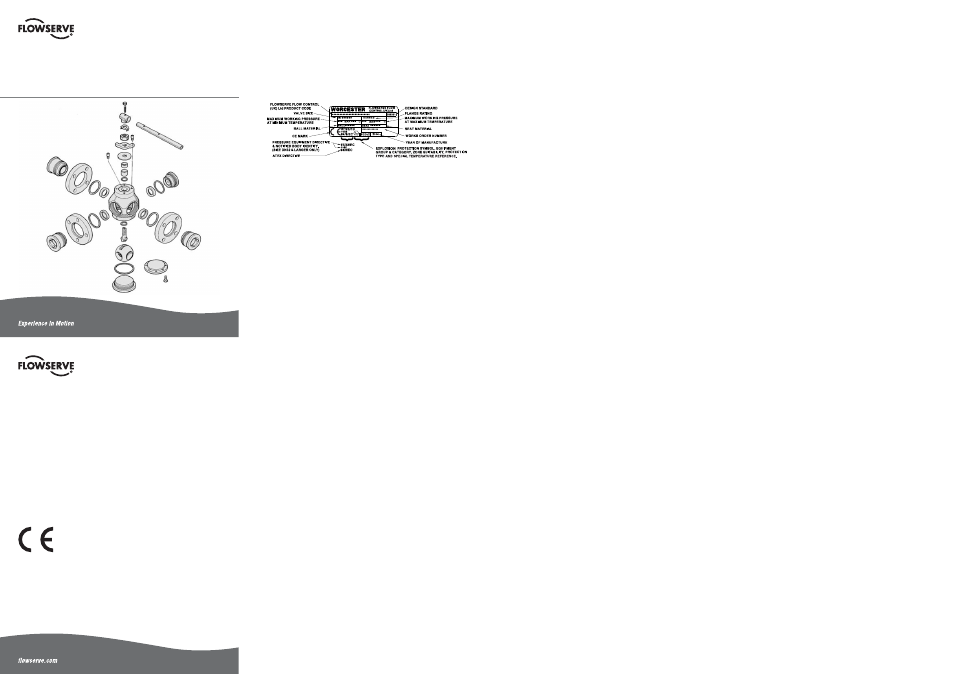
2 VALVE
MARKINGS
Each valve has the following identification information plate attached to the body:
2.1
Pressure Equipment Directive: If the identity plate carries the Pressure Equipment Directive number '97/23/EC' and
the Notified Body identity number '0086' beside the 'CE' mark, the product complies with the Pressure Equipment
Directive 97/23/EC and the Pressure Equipment Regulations 1999 (SI 1999/2001). Without these numbers, the
product is classified as 'SEP' (Sound Engineering Practice) and may only be used within the limitations defined in
tables 6, 7, 8 & 9 of Schedule 3 of the Pressure Equipment Regulations.
2.2
ATEX Directive: If the identity plate carries the ATEX Directive number '94/9/EC' followed by the Explosion
Protection Symbol and codes identifying the equipment group and category, the zone suitability and protection type
beside the CE mark, the product complies with the ATEX Directive and The Equipment and Protective Systems for
Use in Potentially Explosive Atmospheres Regulations 1996.
Definition of identity plate marking above:
'II' = Equipment Group; '2' = Equipment Category; 'G' = Gas Zone suitability (Zones 1 & 2);
'D' = Dust Zone suitability (Zones 21 & 22); 'c' = type of protection i.e. constructional safety
(BS EN 13463-5).
'X' = Special temperature reference (Surface Temperature: As per BS EN 13463-1:2001
paragraph 14.2g, the temperature class or maximum surface temperature cannot be marked on the product as it is
dependant on the operating conditions. However, the maximum/minimum allowable operating temperatures for the
product are marked on the identification plate.
2.3
Should the valve soft trim materials be changed during the course of its operational life it is necessary for this
change to be reflected on the identification plate i.e. material change may impact pressure and temperature limita
tions. Refer to Flowserve Flow Control (UK) Ltd. Technical Sales for details.
2.4
Material traceability markings are hard marked on the valve body and connectors.
User Instructions
Worcester 18/19 Series
Multiway Valves
Installation
Operation
Maintenance
Worcester Controls
Burrell Road,
Haywards Heath,
West Sussex
RH16 1TL
England
Telephone: +44 (0)1444 314400
Telefax: +44(0)1444 314401
Published and Printed by
Flowserve Flow Control (UK) Ltd.
Information given in this leaflet is
made in good faith and based
upon specific testing but does not,
however constitute a guarantee.
© Copyright Flowserve Flow Control (UK) Ltd.
WCEIM0009-01 Replaces PB 18/19 IOM Iss. 5/04
WCEIM0009-01