9refurbishment instructions (cont.), 9refurbishment instructions, Screwed insert type – Flowserve B18 Series Multi-way Valve User Manual
Page 2: 10 valve assembly torques, Bolted connector type
65 - 75
70 - 80
80 - 90
90 - 100
300 - 310
700 - 740
900 - 1065
1500 - 1700
1800 - 2000
150mm (6")
BALL ASSEMBLY
PLATE BOLT
TORQUE
(Nm)
20mm (¾")
9
REFURBISHMENT INSTRUCTIONS (cont.)
c)
Insert the ball into position by sliding it into the body onto the stem tang, ensuring that the foolproof pin engages
correctly with the ball. With a new seal fitted, the ball assembly plate is now positioned into the body and tightened
to the torque specified in Section 10.
d)
The new seats and body seals can now be fitted to the inserts / seat carriers. The application of a little suitable
lubricant (such as mineral oil, a silicon based lubricant or clean grease such as petroleum jelly) to the seats and
seals will help hold them in position and aid 'bedding-in' of the completed valve assembly. NOTE: ensure that the
lubricant used is compatible with the pipeline media.
Ensure that the ball is correctly ported, i.e. not partially open/closed, otherwise seat damage will occur.
Flanged Valves: Position the slip-on flange onto the insert, locate into the body and tighten to the torque specified
in Section 10 using the appropriate 4-pin drive adaptor and drive tools.
Screwed / Weld End Valves: Insert the seat carriers into the body. Slide the assembled body back in between the
body connectors being careful not to damage the seals/sealing faces. Replace the body screws, and tighten diago
nally and evenly to the torque specified in Section 10.
e)
If practical, check for leak tightness and operating torque.
9
REFURBISHMENT INSTRUCTIONS (cont.)
9.3
REBUILDING
Before rebuilding, ensure that the repair kit and/or components used are suitable for the valve requirement. When
rebuilding,
CLEANLINESS IS ESSENTIAL for long valve life.
a)
Stem Assembly - Valves up to and including 25mm Full Bore / 32mm Reduced Bore:
Fit a new stem thrust seal onto the stem shoulder and insert this into the body stem bore from inside the body cavity.
Fit the new gland packing into the top body recess, over the top of the stem, followed by the gland and new disc
springs (with their outer edges touching).
Fit the gland nut, and using the wrench (or other means) to prevent the stem from turning, tighten it down to the
recommended torque.
Operate the stem several times and readjust the gland nut to the specified figure. The locking clip must then be fit
ted correctly, either across the corners or on the flats of the gland nut. The gland nut can be tightened to the next
position to correctly locate the clip (see below). Over-tightening the gland nut will only reduce the life of the stem
assembly. Fit the stop plate, wrench, flow indicator and wrench nut and turn the stem to fully engage the stop pin.
b)
Stem Assembly - Valves 40mm Full Bore / 50mm Reduced Bore and larger
Fit a new stem thrust seal onto the stem shoulder and insert this into the body stem bore from inside the body cavity.
Fit the stem location washer and the new gland packing/s into the top body recess, over the top of the stem, fol
lowed by the gland, flow indicator and stop plate.
Fit the gland nut, and using the wrench (or other means) to prevent the stem from turning, tighten it down to the
recommended torque.
Operate the stem several times and readjust the gland nut to the specified figure. For valves 40 - 50mm Full Bore /
50 - 65mm Reduced Bore, the locking clip must then be fitted correctly, either across the corners or on the flats of
the gland nut. The gland nut can be tightened to the next position to correctly locate the clip (see below). Over-
tightening the gland nut will only reduce the life of the stem assembly.
Turn the stem to fully engage the stop pin.
9
REFURBISHMENT INSTRUCTIONS
Prior to commencing any work on the valve or removing it from line, refer to the 'Health
& Safety' Instructions.
NEVER remove or maintain a valve or joint unless the line has been fully de-pressurised,
drained and where necessary, purged of toxic / explosive / flammable media.
9.1
REMOVAL FROM LINE
a)
Ensure that the valve is correctly supported before attempting to release the securing bolting.
b)
In the case of screwed and weld end versions, the body screws should be removed and the valve body sec
tion taken out of line leaving the end connectors in place.
c)
For flanged versions, the end flange bolting should be removed and the entire valve taken out of line.
d)
The valves should be then taken to a clean, secure working place.
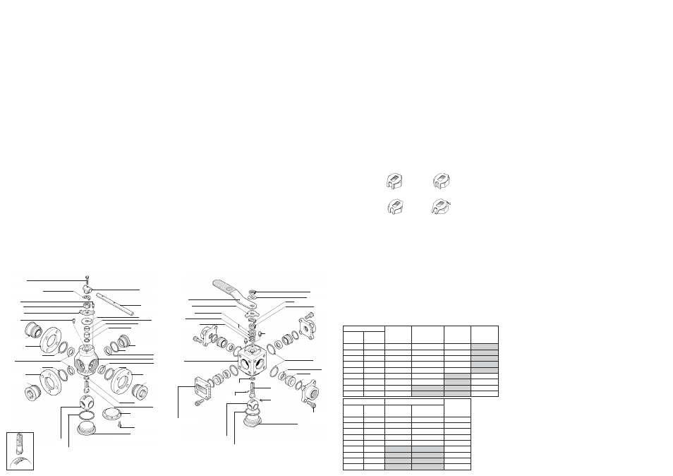
Correct
Incorrect
Incorrect
Correct
SCREWED INSERT TYPE
This Stem/Wrench Build is Typical for Valves 40mm Full Bore
(50mm Reduced Bore) and Larger
Wrench Bolt
Wrench Tube
Flow Indicator
Stem
Ball
Gland Nut
Wrench Head
10
VALVE ASSEMBLY TORQUES
DEFINITIONS
Insert Torque - The torque required to give metal to metal contact with the body and the flange port insert and the
ball assembly insert.
Bolt Torque - The torque required to give metal to metal contact with the body and the body connectors (screwed
and weld varieties), and the ball assembly plate (sizes 65mm Full Bore / 80mm Reduced Bore and larger).
Stem Assembly Torque - The torque required to operate the assembled stem before the ball and seats are fitted.
Gland Nut Torque - The tightening torque to be applied to the gland nut to achieve the stem assembly torque.
Note: these figures are for tightening valves fitted with locking clips and must not be used for tightening self-lock
ing gland nuts.
BOLTED CONNECTOR TYPE
This Stem/Wrench Build is Typical for Valves Up To and Including
25mm Full Bore (32mm Reduced Bore)
Wrench
Stem
Disc Springs
Stop Plate
Wrench Nut
Body
SCREWED/WELDED
BODY CONNECTOR BOLT
TORQUE
(Nm)
BALL ASSEMBLY
INSERT
TORQUE
(Nm)
FLANGE PORT
SCREWED INSERT
TORQUE
(Nm)
REDUCED BORE
18/19
NOMINAL SIZE
FULL
BORE
B18/B19
25mm (1")
32mm (1¼")
50mm (2")
65mm (2½")
80mm (3")
100mm (4")
150mm (6")
200mm (8")
24 - 28
25 - 29
27 - 31
35 - 39
49 - 53
43 - 47
120 - 130
65 - 75
70 - 80
80 - 90
90 - 100
300 - 310
43 - 47
120 - 130
145 - 155
175 - 185
15mm (½")
20mm (¾")
25mm (1")
40mm (1½")
50mm (2")
65mm (2½")
80mm (3")
100mm (4")
6 - 10
6 - 10
8 - 12
15 - 20
15 - 20
150mm (6")
20mm (¾")
PTFE
BUILD
STEM
ASSEMBLY TORQUE
GRAPHITE
BUILD
REDUCED BORE
18/19
NOMINAL SIZE
FULL
BORE
B18/B19
25mm (1")
32mm (1¼")
50mm (2")
65mm (2½")
80mm (3")
100mm (4")
150mm (6")
200mm (8")
8 - 12
8 - 12
13 - 18
19 - 24
19 - 24
4 - 6
4 - 6
6 - 8
8 - 11
8 - 11
18 - 22
18 - 22
23 - 28
23 - 28
15mm (½")
20mm (¾")
25mm (1")
40mm (1½")
50mm (2")
65mm (2½")
80mm (3")
100mm (4")
GLAND NUT TORQUE
Stop Plate
Stop Pin
Stop Pin
Gland Nut Locking Clip
Gland
Gland Packing
Blank Port Insert
Flange Port Insert Seal
Seat
Body
Flange Port Insert Seal
Seat
Slip Flange
Flange Port Insert
Hex Head Screw
Stem Thrust Seal
Ball Assembly Plate Seal
Slip Flange
Flange Port Insert
Flange Port Insert Seal
Flange Port Insert Seal
Seat
Flange Port Insert
Slip Flange
Detail showing stem
location pin for correct
orientation of ball to stem.
NOTE: For 15-50mm F.B. & 20-65mm R.B. valves, one gland packing is used.
For 65-150mm F.B. & 80-200mm R.B. valves, two are used.
Socket Head
Cap Screw
Ball Assembly Insert
Ball
Body Seal
Blanking Plate
Thrust Seal
Foolproof Pin
Foolproof Pin
Seat Carrier Seal
Seat Carrier
Seat
Flow Indicator
Body Seal
Gland Nut Locking Clip
Gland Nut
Stop Pin
Gland Packings
(40-50mm F.B. & 50-65mm R.B. Only)
Ball Assembly Plate
(15-50mm F.B. & 20-65mm R.B. Only)
Ball Assembly Plate
(65-150mm F.B. &
80-200mm R.B. Only)
Stem Location Ring
(65-150mm F.B. & 80-200mm R.B. Only)
Gland
9
REFURBISHMENT INSTRUCTIONS (cont.)
9.2
DISMANTLING
a)
Flanged Valves. Flange Insert Removal: 15 to 50mm Full Bore and 20 to 65mm Reduced Bore:
The flange port inserts should be removed using the appropriate four-pin drive adaptor. On these sizes of valves it
should be possible to remove the inserts using standard workshop air torque / impact wrenches. Remove and dis
card all seats and body seals.
b)
Flanged Valves. Flange Insert Removal: 65 to 150mm Full Bore and 80 to 200mm Reduced Bore:
Due to the input torque requirement, it will be necessary to use a torque multiplier or hydraulic drive tool, in con
junction with the appropriate drive adaptor. It is recommended that the drive tool assembly is firmly clamped in
position during the initial breaking out of the insert threads to ensure that the drive adaptor does not 'cam-out' of
the flange port inlet drives. A small flypress or similar is particularly suited to this job. Should the drive tool require
a reaction point, it is recommended that this is located on the clamping device to prevent accidental damage to the
components. Remove and discard all seats and body seals.
c)
Screwed / Weld End Types: Extract the push-in seat carriers complete with associated seats and body seals.
Discard the seats and seals.
d)
Ball Assembly Plate Removal: For valves up to and including 50mm Full Bore and 65mm Reduced Bore, it will be
necessary to use the appropriate four-pin drive tool and wrench. For larger valves the ball assembly plate is
secured by bolts, and requires no special tools. Remove the ball and body seal, and discard the seal.
e)
To dismantle the stem assembly:
For valves up to and including 25mm Full Bore and 32mm Reduced Bore, remove the following:
Wrench Nut
Flow Indicator
Wrench
Stop Plate
Gland Nut Locking Clip
Gland Nut
Disc Springs
Gland
For valves 40mm Full Bore / 50mm Reduced Bore and larger, remove the following:
Wrench Bolt
Wrench Head and Tube
Gland Nut Locking Clip (40 - 50mm Full Bore / 50 - 65mm Reduced Bore only)
Gland Nut
Stop Plate
Flow Indicator
Gland
Withdraw the stem from inside the body and remove the stem thrust seal from the body recesses. The gland pack
ing and stem location washer (where fitted) can now be removed from the top body recess.
All components not replaced by items in the repair kit should be thoroughly cleaned and stored in a secure area. All
sealing surfaces on the body, inserts, connectors, blanking plates, ball assembly plates, ball and stem should be
checked for corrosion, erosion and scratches. If any damage is found, or if there is any doubt over the suitability of
the part, then it must be replaced.
g)
Cleaning of parts may be carried out using a suitable degreasing agent. Hard deposits can be removed using stain
less steel wire wool. Again, care should be taken not to damage any of the sealing surfaces.