Flowserve RG Series Standard Actuator User Manual
Page 4
4
®
User Instructions RG Series Standard Actuator - AXENIM0122-00 12/09
Introduction
The RG Series is a fully modular design, scotch-yoke ac-
tuator; with torque range from 2000Nm to 250,000Nm
(2,800 in-Lbs to 2.2 M in-Lbs) in eight models, RG1
through RG8, with maximum actuator torque and
mounting base in compliance with ISO 5211.
The RG series Spring Return Actuators, in contrast with
R-series, use Pull-to-Compress the spring design.
2
Installation
2.1
All actuators are factory lubricated for life, but still
should be protected from the elements and stored in-
doors until ready for use. The ports of the actuator are
plugged as supplied from the factory. If actuators are
stored for a long period of time prior to installation, fol-
low the Long Term Storage instructions.
2.2
Prior to assembly, manually open and close valve (if
possible), to ensure freeness of operation. Be sure,
valve and Automax actuator rotate in the same direction
and are in the same position (i.e., valve closed, actuator
closed).
2.3
Check the mounting surfaces, the stem adaptor and
the bracket to assure proper fit. Secure the valve in the
closed position with the stem vertical. Bolt the bracket
to the valve and place the stem adaptor on the valve
stem. Position the actuator over the valve and lower, to
engage the stem adaptor to the actuator’s bore. Con-
tinue to lower until the actuator seats on the bracket
mounting surface. In order to align the bolt holes, it
may be necessary to loosen the valve-to-bracket bolting
to allow more play in the bracket. The mounting bolts
should easily fit into the bolt holes without any binding.
If needed, turn or stroke the actuator a few degrees and/
or adjust the actuator travel stops. Bolt the actuator to
the bracket.
2.4
Adjust the travel stop bolts of the actuator for the proper
open and closed valve positions, per valve manufactur-
er’s recommendations. Pneumatically stroke the actua-
tor several times to assure proper operation. The stem
adaptor should not bind during operation. If the actua-
tor is equipped with an UltraSwitch or other accesso-
ries, adjust them at this time.
2.5
To prolong actuator life use only clean, dry plant air. Lu-
bricated air is not required, however it is recommended
particularly for high cycle applications. Do not use lubri-
cated air with positioners.
CAUTION! Lifting bolts holes on the actuator are for
lifting the actuator modules only with eye bolts, not a
complete valve and actuator assembly.
3
Travel Stop Adjustments
All actuated valves require accurate travel-stop adjust-
ments at both ends of the stroke to obtain optimum
performance and valve seat life. The accumulation of
tolerances in the adaption of actuators to valves is such
that there must be a range of adjustments for both ends
of the stroke to achieve optimum performance.
The RG actuators have travel stop adjustments in both
the clockwise and counter-clockwise directions. The
+/- 3 degree adjustment feature provides shaft rotation
from 84 to 96 degrees.
4
Maintenance Instructions
4.1
Disassembly Instructions
4.1.1 Disconnect all air and electrical supplies from actuator.
4.1.2 Remove all accessories from actuator and dismount ac-
tuator from valve.
4.1.3 Drawing References: Drg # 263188, Drg # 263189
4.2
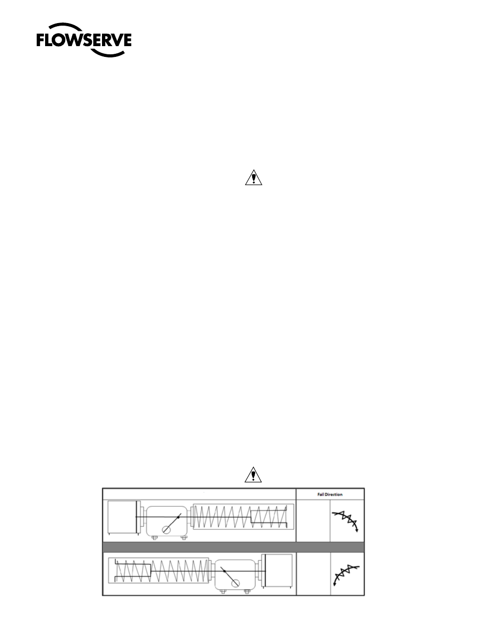
Spring Module (see Fig.: 1)
CAUTION! Personal Injury may result if Step 2 is at-
tempted before Step I is completed.
Fig.: 1 Spring Module
4 2
4 2
CW
CWW
Actuator Configuration