Commissioning, Wiring – Flowserve NRG 111-11 User Manual
Page 17
17
Apply mains voltage to level switch NRS 1-7.
Commissioning
Make sure that the electrode NRG 111-11 is connected to the level switch NRS 1-7 according to the
wiring diagram. Fig. 12
Check wiring
Apply mains voltage
Wiring
– continued –
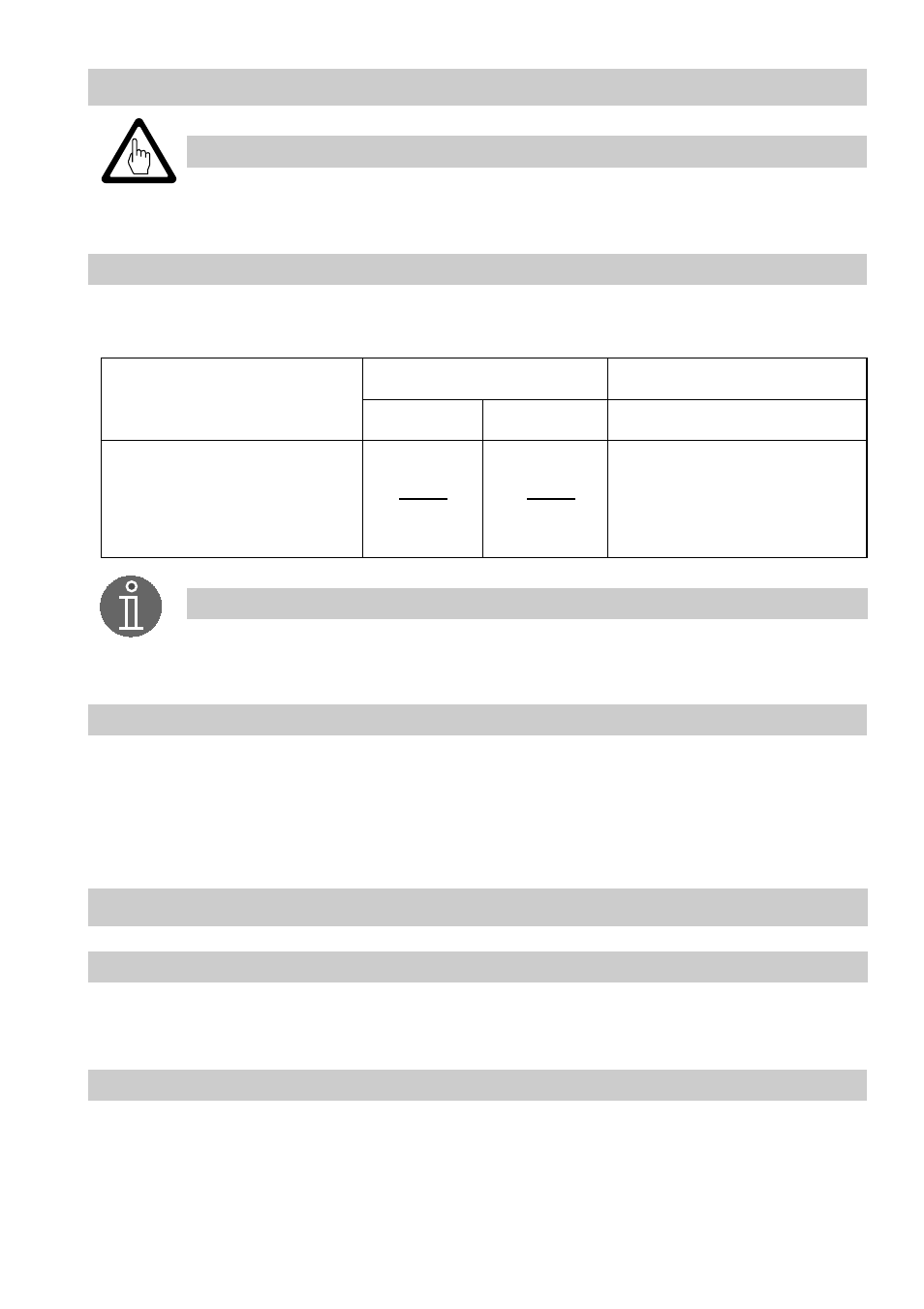
Voltage table
Use this voltage table to check whether the level electrode is submerged or if there is a malfunction.
Observe the wiring diagram of the NRS 1-7, fig. 12
Note
■
The self-checking routine of the amplifier NRS 1-7 reduces U
1-2
every 40 sec.
to 0 volt!
■
Use sealing plug for cable entry L if only one cable runs to the terminal box.
Insert sealing plug supplied with the electrode (IP 65)!
Tools
Attention
■
Screwdriver for cross head screws, size 1
■
Screwdriver for slotted screws, size 2.5, completely insulated according to DIN VDE 0680-1
■
Open-end spanner 18 (19) mm A. F.
U
1-2
10 V
eff
0.5 µS/cm,
C = 0.13 cm
-1
U
1-4
U
2-4
submerged
exposed
malfunction (submerged / alarm)
U
1-2
2
<
U
1-2
2
≥
U
1-4
≤