Flowserve NAF-Duball ball valves User Manual
Page 5
5
6.
Fit the ball in the body half (1) - Fig. 4 - and then
fit the other body half (2). Make sure that the
centrepunch marks made in accordance
with item 6 in section 9.1 are lined up.Tighten
the bolted joint of the two halves of the body
alternately in several stages, and finally tighten
according to the torque as below.
7.
Operate the valve between the closed and open
positions.
8.
If possible, pressure test the valve with water to
check its tightness - Fig. 7.
Make sure that the
cavities of the valve are properly filled with
liquid before pressure testing.
Bolt
Torque NM
Bolt
Torque Nm
M12
76
UNC 1/2”
89
M16
187
UNC 5/8”
175
M20
364
UNC 3/4”
308
M24
629
UNC 7/8”
493
UNC 1”
737
Pressure Class
Test pressure, bar
Open valve
Closed valve
PN10
15
11
PN25
38
28
PN40
60
44
Class 150
30
22
Class 300
75
28
Fig 6
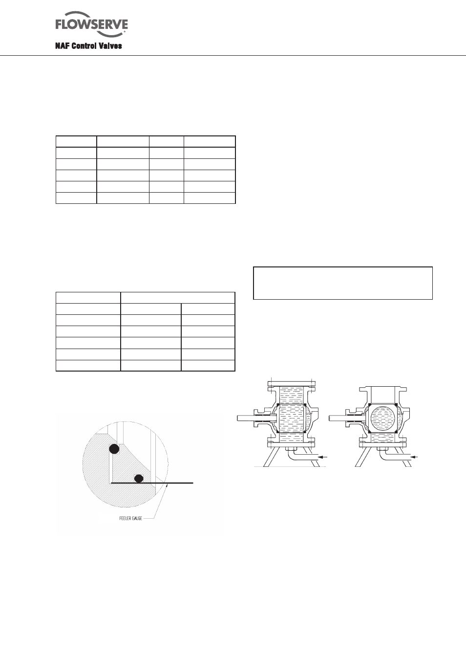
9.4
T-version
Seatring with double o-rings must be vented during
mounting. The easiest way to do this is to use a feeler
gauge - see fig 6.
9.5 Valves with chronium-plated ball and seat rings
in alloy 6
1. Check the sealing surfaces of the seat rings.
A groove on the inside of the facilitates withdrawal.
Minor damage to the rings can be rubbed down
with fine emery cloth. Check the rings on a face
plate to ensure that they are perfectly flat. Don’t lap
the rings and the chromium-plated ball together.
Change the rings if they are severely damaged.
2. Inspect the sealing surface of the ball. Minor
damage may be rubbed down with fine emery
cloth. If the existing ball must be used for a further
period of time, remove all sharp edges, dents and
irregularities with a fine file or emery cloth. If the
ball is severely damaged, the complete ball set
must be replaced.
3. Fit the sealing ring (22 alt. 31) behind the seat
rings.
N.B. the sealing rings must be fitted with the
sharp edge towards the body half (see Fig. 4).
4. Grease the ball with a suitable grease, such as
Klüber Unisilicone L641 or similar.
5. Continue assembling the valve as described in
items 5 - 9 in section 9.3.
Valve open
Valve closed
Sealing flange
Water
Water
Fig. 7. Pressure test of the valve with water