Kämmer, 63 mm, Range adjust- ment screw – Flowserve 4 Series Kämmer Pneumatic and Electropneumatic Actuators User Manual
Page 18: Gauge (scale 1:1) dim. "a, Positioner spring adjusting nut actuator stem, Gauge set screw, 8calibration calibrate actuator
18
Flow Control Division
Kammer Control Valves
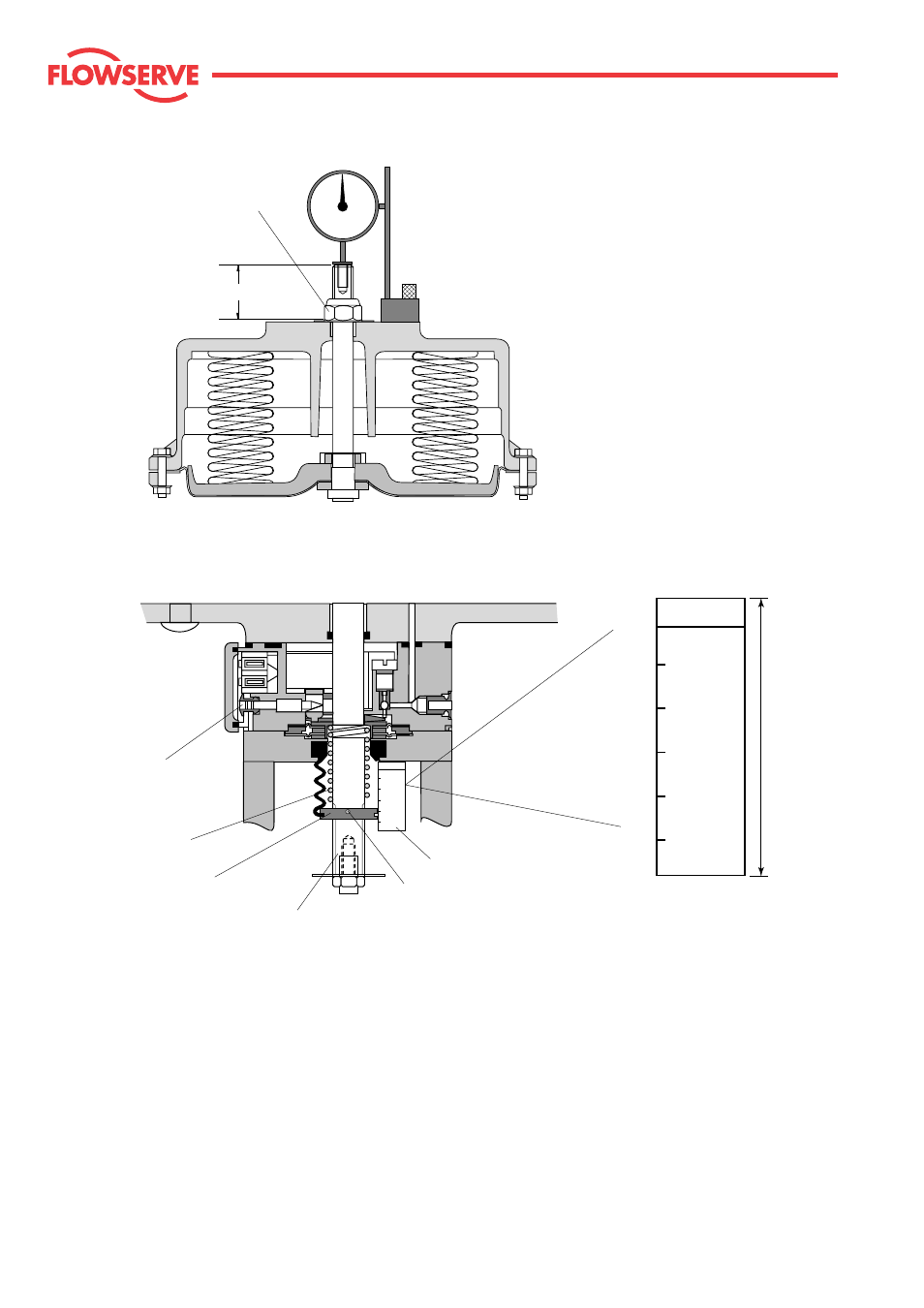
Fig. 14: Dial gauge
Adjust positioner spring with gauge
Fig. 15
KÄMMER
39D>
37/38/39
39D<
39D>
37/38/39
39D<
38-2
39D>
38-2
39
39D<
10
10
10
20
20
20
10
40
20
40
40
Type
H
Positioner spring
Adjusting nut
Actuator stem
Range adjust-
ment screw
(max. 3 turns)
Gauge
Set screw
Gauge (scale 1:1)
Dim. "A"
8
Calibration
Calibrate actuator
(actuator without adjustable positioner spring)
8.1
Range adjustment
See nameplate for signal range, supply pressure
and stroke.
8.1.1
Connect air supply to the "SUPPLY" port of the
actuator and an adjustable signal source to the
"SIGNAL" connection. Attach a dial gauge to the
actuator (see Fig 14).
8.1.2
Undo the zero adjustment locknut until it is a few
threads free of the actuator housing. Set the
signal to the low end value (e.g. 0,2 bar or 4 mA).
Adjust the dial gauge to zero.
8.1.3
Set the signal to the high end value (e.g. 1,0 bar or
20 mA).
Zero adjustment locknut
KÄMMER
39D>
37/38/39
39D<
39D>
37/38/39
39D<
38-2
39D>
38-2
39
39D<
10
10
10
20
20
20
10
40
20
40
40
Type
H
63 mm