Kammer control valves – Flowserve 4 Series Kämmer Pneumatic and Electropneumatic Actuators User Manual
Page 23
23
Flow Control Division
Kammer Control Valves
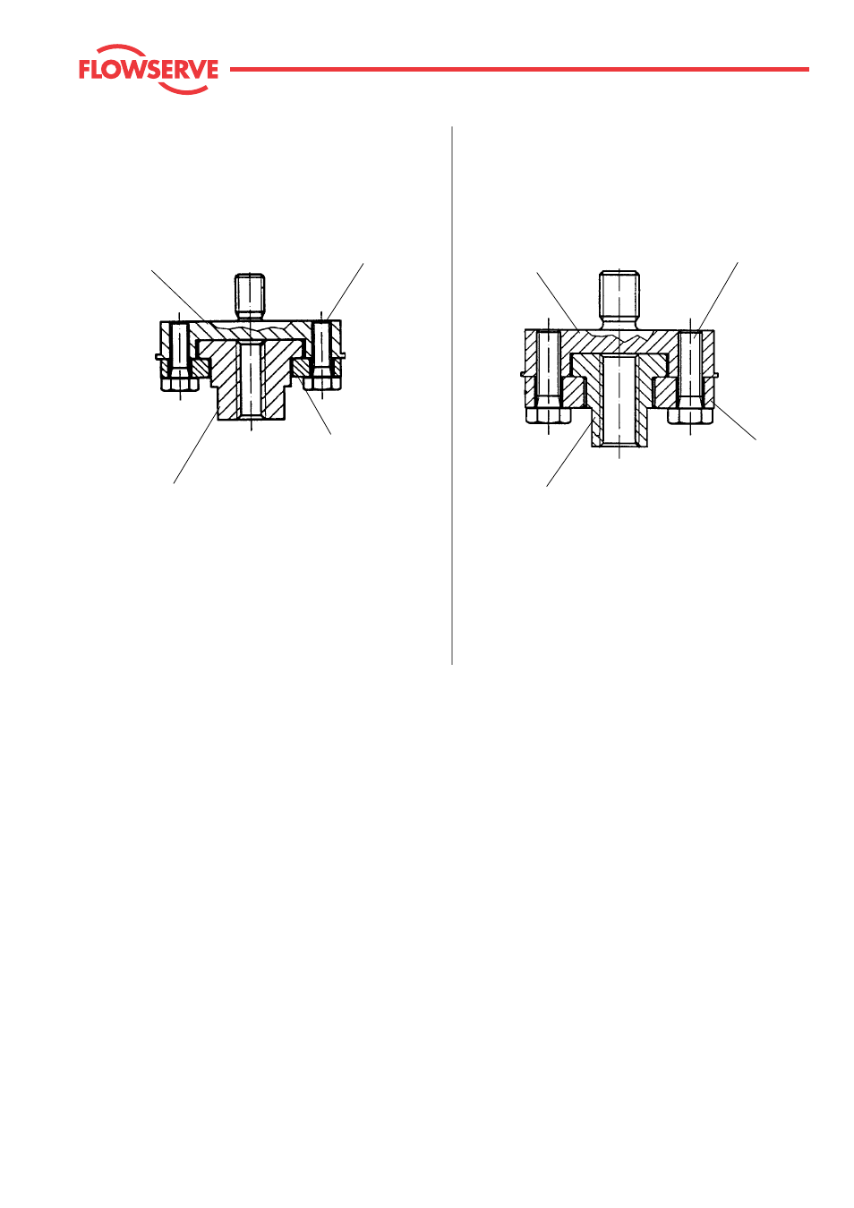
Lower coupling half
Part-No. 0 37 01 07 00
Lower coupling half
Part-No. 0 36 01 07 00
Coupling insert M 4 Part-No. 0 37 01 08 00
Coupling insert M 6 Part-No. 0 37 01 09 00
Coupling insert M 10 Part-No. 0 37 01 10 00
Coupling assy. M 10 / M 6 Part-No. 0 36 01 01 00
Coupling assy. M 10 / M 10 Part-No. 0 36 01 02 00
Screw, M 6 x 20 (2x)
Part-No. 0 10 02 22 00
Screw, M 4 x 12 (2x)
Part-No. 0 10 02 05 00
Coupling for actuators with 2 yoke rods
Coupling for actuators with 3 yoke rods
Coupling insert M 6 Part-No. 0 36 01 09 00
Coupling insert M 10 Part-No. 0 36 01 08 00
Upper coupling half M10
Part-No. 0 36 01 06 00
Upper coupling half M6
Part-No. 0 37 01 06 00
Coupling assy. M 6 / M 4 Part-No. 0 37 01 03 00
Coupling assy. M 6 / M 6 Part-No. 0 37 01 01 00
Coupling assy. M 6 / M 10 Part-No. 0 37 01 02 00