Automax buswitch, Profibus-dp – Flowserve BUSwitch-Profibus-DP User Manual
Page 2
LML0012-0 8/99
Page 2 of 6
©1999, Flowserve Corporation, Provo, Utah
Flowserve Corporation
Flow Control Division
Automax BUSwitch
TM
– Profibus-DP
765 South 100 East
Provo, Utah 84606
www.flowserve.com
Phone: 801 373 3028
Facsimile: 801 489 2228
Email: [email protected]
Lubrication
All BUSwitch™ spool valves are pre-lubricated and
will operate dry (with no additional lubrication). The
use of lubricated air will not interfere with the
BUSwitch’s functioning. If air lubrication is used, the
oils listed below are popular, easily obtainable, fluids
that are recommended for use with the BUSwitch
spool valve: Gulf Harmony 47, Mobil DTE Medium,
Shell Tellus 29, Texaco Rondo B, Sohivis 47 and
Sunnis 921. Many other lubricants are acceptable
providing they do not contain detergents that will
attack Buna-N or Viton Seals.
Electrical Connections
CAUTION
To prevent ignition of hazardous atmospheres,
keep cover bolts tight while circuits are live.
Disconnect supply circuit before opening.
Entry into the BUSwitch housing is made through
three ½” NPT conduit entries. All electrical
connections (power, data, external alarm, open and
close solenoids) are made to captive screw cage
terminal strips located on the Profibus-DP Interface
board (XA0231). BUSwitch models with an internal
pilot valve will have the valve connected to the
appropriate circuit board terminals by the factory.
For dual solenoid applications, connect the
respective solenoids to the terminal strip locations
marked ‘OPEN’ and ‘CLOSE’. External power (24
VDC) is connected to the indicated location.
CAUTION
BE SURE TO OBSERVE CORRECT POLARITY
OF THE EXTERNAL POWER CONNECTIONS
OR DAMAGE TO THE PRINTED CIRCUIT
BOARD WILL OCCUR!
A ‘dry-contact’ device can be connected to the
terminals marked ‘EXTERNAL ALARM’, the
meaning of which is determined by the customer.
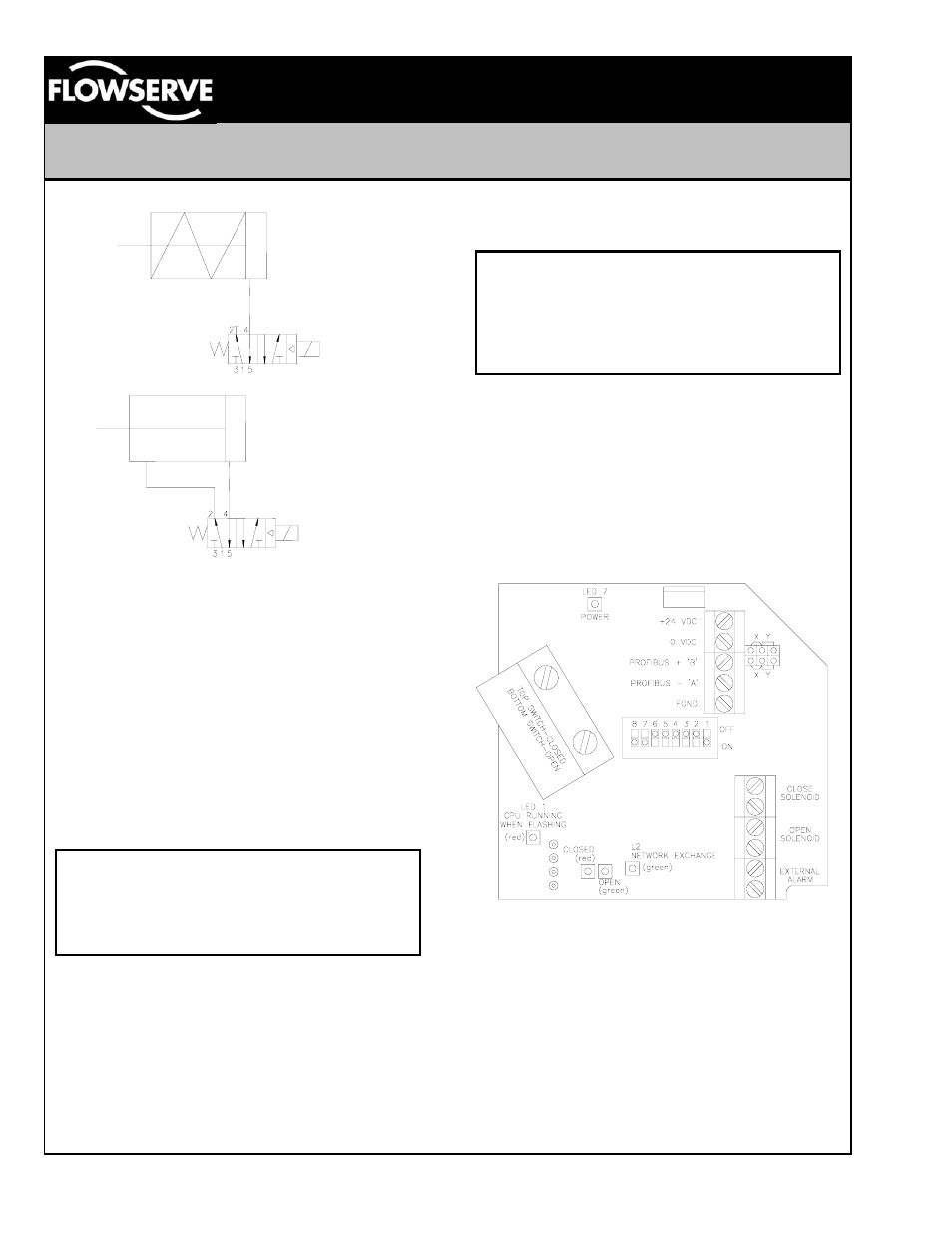
Refer to figure three. The data cable connection is
made to the locations marked PROFIBUS + B and
PROFIBUS – A, observing polarity. If this is the last
device on the segment, move the shorting jumpers
to the Y position to enable the termination resistor.
Refer to figure three for data cable connection
locations.
Profibus-DP Interface Card (XA0231)
Figure 3
For hazardous locations, Underwriters Laboratories
(UL) and the National Electric Code (NEC) require
an approved sealing fitting within eighteen inches of
the switch enclosure. Sealing fittings are not
required for Division 2 non-incendive applications.
Open conduit entries must be closed after
installation using a close-up plug approved for
hazardous locations. Conduit and plugs must
engage a full five threads. Flowserve can provide
the sealing fitting with a union and junction box for
‘daisy chain’ wiring applications.
Figure 1
Figure 2