Automax buswitch, Profibus-dp – Flowserve BUSwitch-Profibus-DP User Manual
Page 4
LML0012-0 8/99
Page 4 of 6
©1999, Flowserve Corporation, Provo, Utah
Flowserve Corporation
Flow Control Division
Automax BUSwitch
TM
– Profibus-DP
765 South 100 East
Provo, Utah 84606
www.flowserve.com
Phone: 801 373 3028
Facsimile: 801 489 2228
Email: [email protected]
A simple algorithm that can be used to set the board
to a specific address is.
1. Put switches 2 through 8 into the OFF position.
2. Determine the address where the BUSwitch will
reside. This value will be known as the ‘target’
value.
3. Referring to Table 3, locate the switch with the
highest decimal value that is less than or equal
to the target value. Move that switch to the ON
position. For example if the target value is 33,
switch #3, with a decimal value of 32, would be
moved to the ON position.
4. Subtract the decimal value of the switch that
was just turned on from the target value. The
difference, if it is not equal to zero, will become
the new ‘target’ value. From the example
above, 1 will be the new target value (33-32=1).
5. Repeat steps 3 and 4 until the difference
between the switch value and the target value is
zero. Upon application of power to the board,
the address will be read from the switches.
Communication of the operating parameters to the
BUSwitch is accomplished by reading and writing of
six, 16-bit words. To ensure that the BUSwitch
sends and receives the correct data, all six words
should be read or written anytime one of the
parameters is changed.
Board Indicators
The Profibus-DP Interface Board (XA0231) contains
several indicators that are helpful when initially
configuring the device or when troubleshooting.
Refer to figure three for the locations of the
indicators.
LED 7 – Power Illuminated when 24 VDC is
present.
LED 1 – CPU Running When Flashing
This
indicator will flash red approximately every 2
seconds to indicate that the microprocessor is
operating normally. If the indicator glows steadily or
does not come on, remove device power for 10
seconds and then reapply to reset.
L2 – Network Exchange This indicator will be
green when communication with the device is taking
place over the network.
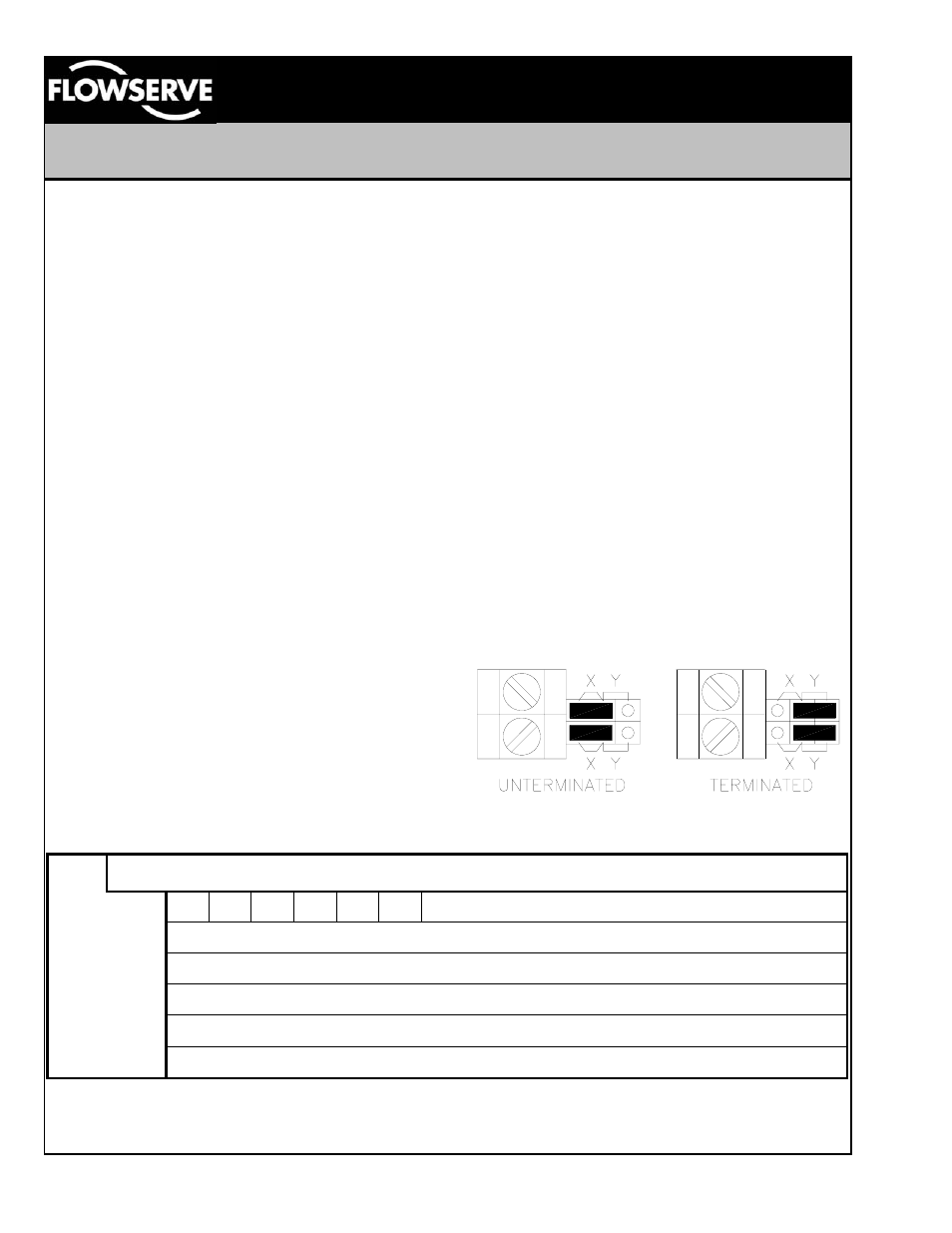
Terminations
For proper communication to take place, each end
of the network segment must have terminators.
Terminators are resistive devices used to insure the
proper network impedance is maintained. In most
systems, one of the terminators will be located at the
PLC. The other terminator is located at the last
device on the segment. If the BUSwitch is the last
device on the segment, move the two jumpers on
the ‘X” locations over to the ‘Y’ locations to enable
the on board terminator. If the BUSwitch is located
within the center of the segment, the jumpers should
be set on the ‘X’ locations. Refer to figure five.
Figure 5
BUSwitch Input Data Packet
Word
↓
Bit
→
1 2 3 4 5 6 7 8 9 10 11 12 13 14
15 16
1
OP CL RS AL FA FO
Reserved
2
Odometer Limit (Most significant word)
3
Odometer Limit (Least significant word)
4
Oneshot Duration ( 50 millisecond ‘ticks’ )
5
Valve Opening Response Timeout ( 50 millisecond ‘ticks’ )
6
Valve Closing Response Timeout ( 50 millisecond ‘ticks’ )
Table 4 – Input Data Packet