Flowserve Automax XCL UltraSwitch User Manual
Page 9
9
Automax XCL/XML Switch Box User Instructions FCD AXENIM0120-13-A4 02/15
flowserve.com
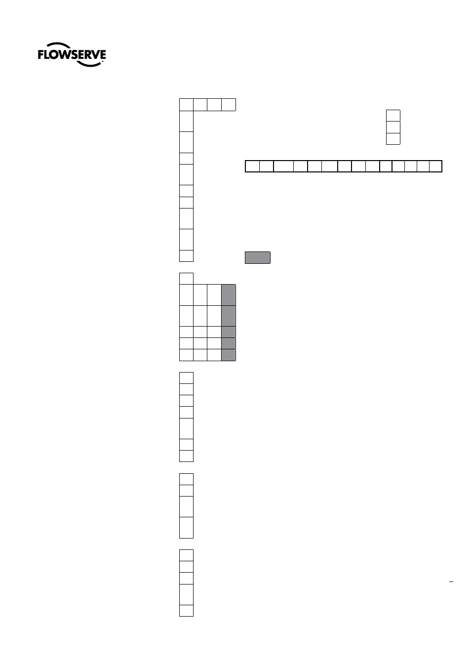
F = Switch options (qty of switches)
0
1x 2x 4x
19
- ATEX II 2 G EEx d IIB T4-T6, II 2 D
Ex tD A21 IP65
25
- IEC Ex approval Ex d IIB T4-T6, II 2
D Ex tD A21 IP65
26
- Inmetro BR Ex d IIB T5
27
- cCSAus IS class I, II, III Div1, Gr.AB-
CDEFG T5
28
- cCSAus Cl.I, Div2, Gr. A,BC&D.
30
- Kosha Ex d IIB T5
M1
- Metal plate cCSAus Cl.I, Div2, Gr.
A,BC&D.
M2
- Metal plate cCSAus Cl.I, Div1, Gr.CD
/ Cl.II, Div1, Gr.EFG, Cl.III.
M3
- Metal plate ATEX II 2 G EEx d IIB T5
H = Analog Output *
0
- None
T
- 4-20 mA transmitter (F= 00, M1, MG
& N8 only)
D
- 180 deg 4-20 mA transmitter (F= 00,
M1, MG & N8 only)
A
- 0-1k Ohm Pot
B
- 0-5k Ohm Pot
C
- 0-10k Ohm Pot
I = Wiring options
0
- None
1
- Brad Harrison Connectors - 3 pins
2
- Brad Harrison Connectors - 5 pins
3
- Brad Harrison Connectors - 7 pins
H
- Heavy Duty Terminal Block (Max 8
contact points)
P
- Sealed/Potted Leads**
R
- Westinghouse special
J = Minimun extra terminals
2
- 2 (Standard***)
4
- 4 (Optional)
6
- 6 (Optional, not possible for all
switch options)
8
- 8 (Optional, not possible for all
switch options)
K = Accessories
0
- None
L
- Cover bolts lubricated with grease
N
- No Silicone
P
- 180’ pot ( for analog options: A, B,
C)
V
- Viton O-rings
L = Housing/Surface treatment
0
- Black Polyester Powdercoat
E
- White Epoxy Coated
W
- White Epolon II
Example:
P
N
XCL
U
2 M1 - 18
-
0
0
2
0
0
*Transmitter option available for switch options 00, M1, MG, N8 only,
maximum number of switch elements is (2)
**When ordering potted leads, specify the conduit (left or right),
number of leads, length, and color of wires
***Some models have more than (2) open terminal locations open as
standard. Consult factory for details.
No possible combination/option
NOTES:
1. MA switch element must be ordered with qty. (2) switch elements.
MD and MS switch elements must be ordered with qty. (4) switch
element.
2. Certifications:
Valid certification codes for Mechanical Switches ( options M1,
MA, MD, MS, MC, MG, M3 and MB) include -14, -18, -19, -25,
-M1. Valid certification codes for Proximity Switches (options P4,
P5, PE, PP, PL, PT, N8, N9, NQ, NR, NS, NJ and NP include -14,
-18, -19, -25, -M2. Valid certification codes for Analog Output
(options T, D, A, B, D) include -14,-18,-19,-24, -M1.
3. Transmitter option available for switch options 00,M1,MG, N8 only,
maximum number of switch elements is (2).
4. When Ordering potted leads, specify the conduit (left or right),
number of leads, length, and color of wires.
5. Some models have more than (2) open terminal locations open as
standards. Consult factory for details.
6. Switch option FN(Device Net) is not approved for ATEX or IECEx.
7. Valid switch options for Intrinsically Safe (-27 code) are MG, PE,
PT, P4, N8, NQ, NP.
8. Heavy Duty Terminal blocks only available for two (2) SPST or two
(2) SPDT type switches maximum. (8 terminal points maximum).
Example:
PNXCLU2M1-18-00200 = Automax brand, NAMUR shaft, XCL,
Ultradome indicator, (2) SPDT mechanical switches CSA and ATEX
certifications.