Flowserve 4-75 Position Indicator User Manual
75 position indicator, Installation, operation and maintenance, Description
4-75 Position
Indicator
Installation, Operation and Maintenance
FCD WCAIM2070-00 (Part 06525)
���������������������������
1. Description
The 4-75 position indicator is designed to be used with and mounted
in the Series 75, 120 VAC actuator with many of its standard options
including the I-75 Interface Kit and the DFC17 controller. Its output
is suited for 4-20 mA DC meter with 0-100% scale (such as General
Electric Type GE185), which is not part of the package. If properly
calibrated, it indicates actuator shaft position from closed (0°, 0%)
to open (90°, 100%). It is combined with standard Potentiometer
Kit, which supplies information on shaft position. If feedback poten-
tiometer is required for other functions such as remote resistance
indication, or with a DFC17 controller, a dual Potentiometer Kit
must be used. Each potentiometer can serve only one function. For
installation procedures and wiring of potentiometer, see Potenti-
ometer Kit Instructions (WCAIM2067) or 75 Actuator instructions
(WCAIM2013) or DFC17 instructions (WCAIM2026). These instruc-
tions can be obtained from your local distributor/supplier or online
at www.flowserve.com.
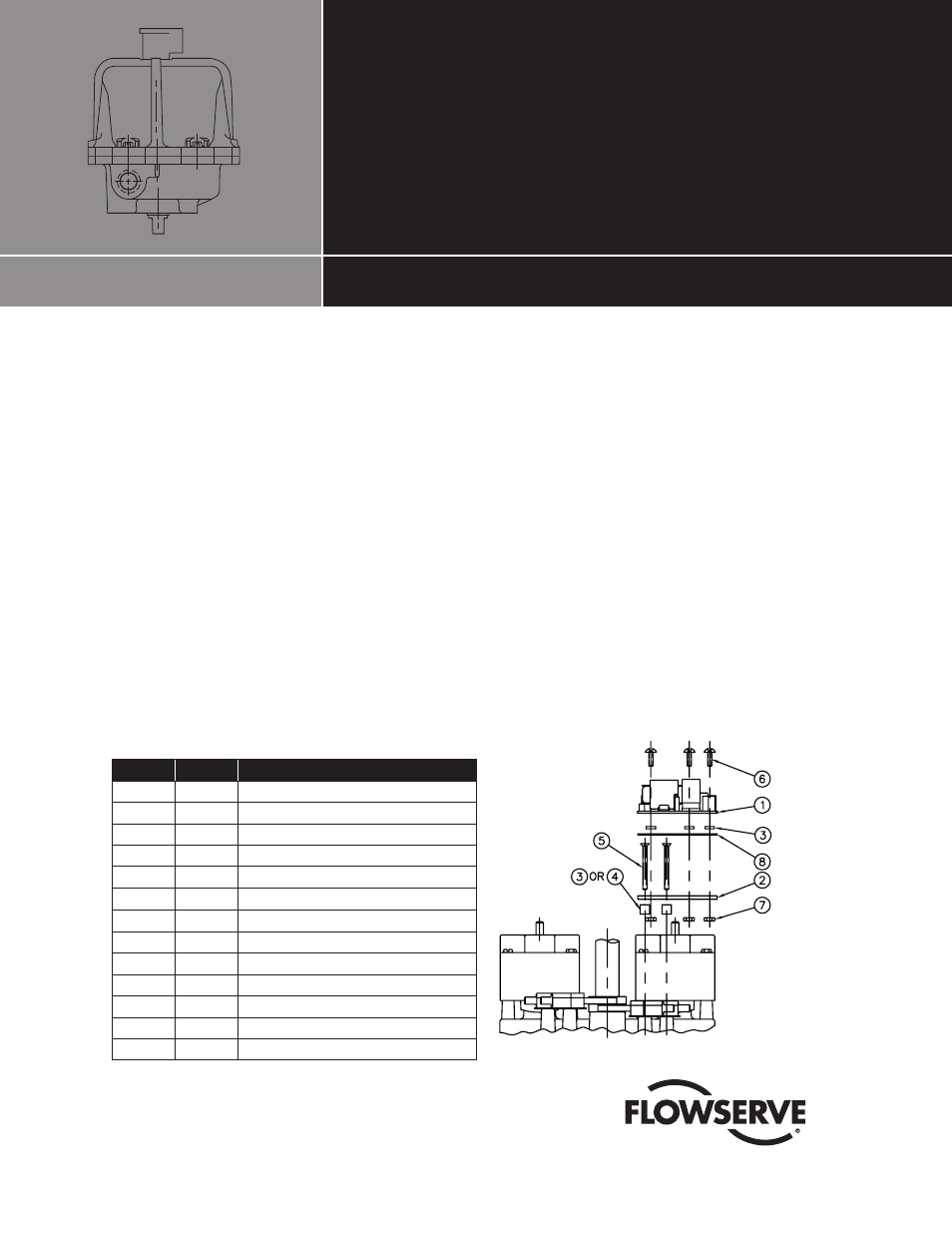
Parts included in kit:
Item
Qty.
Description
1
1
Circuit Board
2
1
Mounting Plate
3
5
Spacers (.06")
4
2
Spacers (.25")
5
2
#4-40 x 1¼" F.H. Screws
6
3
#4-40 x
3
⁄
8
" R.H. Screws
7
3
#4-40 Nuts
8
1
Insulator
9
3
Cable Ties (Not Shown)
10
1
Potentiometer Kit (Not Shown)
11
1
Wiring Label (Figure 2)
12
1
Wire—White (Not Shown)
13
1
Closed End Splice (Not Shown)
2. Installation
(See Figure 1.)
NOTE: This instruction sheet shows standard installation and wiring
of a 4-75 Position Indicator only. For 25/30 75 actuator, mount
4-75 assembly on top of limit switch(es) using same procedure as
shown below.
Remove the two mounting screws from right limit switch(es), as
viewed from terminal strip. Place two spacers (4) (use two spacers
(3) for M1 or M2 option) between limit switch and mounting plate
(2), and fasten mounting plate in place with two longer flat head
screws (5). Locate insulator (8) on top of mounting plate. Using
three spacers (3) to separate circuit board (1) from mounting plate
(2) and insulator (8), mount circuit board using #4-40 x
3
⁄
8
round
head screws (6) and nuts (7). Check entire assembly and firmly
secure all screws.
Figure 1—10-23 75 Installation