Adjustment and calibration, Repair – Flowserve 4-75 Position Indicator User Manual
Page 3
Flow Control
Worcester Actuation Systems
FCD WCAIM2070-00
4-75 Position Indicator
3
4. Adjustment and Calibration
The feedback potentiometer has to be adjusted to obtain the proper
resistance range. With the actuator either in the OPEN (full coun-
terclockwise) or CLOSED (full clockwise) position, and power off,
rotate the face gear, thus turning the potentiometer shaft, until the
resistance between the white/black lead and the green lead (actuator
full counterclockwise), or the white/black lead and the purple lead
(actuator full clockwise), respectively, as measured by ohmmeter, is
between 80 ohms and 90 ohms.
NOTE: It is not necessary to loosen or remove face gear snap ring(s)
to rotate gear; it is a friction fit. If for any reason any snap ring is to
be removed, do not overstretch it; use the minimum opening needed
to allow it to slip over the gear.
Power the actuator to the opposite position from where resistance
was measured. At this position, with power off, measure the resis-
tance at the same terminals as stated above. The resistance reading
should be greater than 700 ohms. If not, then power actuator back to
original position and adjust pot again, as stated in paragraph above.
If unsuccessful in getting proper resistance readings, pot is defective
and should be replaced.
NOTE: For units with a DFC17 controller, do not use above instruc-
tions, as adjustment and calibration are accomplished through
controller circuit board only. See DFC17 IOM (WCAIM2026).
To obtain proper 4-20 mA output, the indicator board output has to
be calibrated. Using an ammeter connected to actuator terminals
5 (positive) and 6 (negative)—or for DFC17 controller, connected
directly to red and black wires of indicator board—adjust the two
potentiometers R4 and R5 on the board. With the actuator in the
closed position (0%), adjust R5 potentiometer (adjacent to the num-
ber “4” etched on the circuit board and closest to terminal block) to
obtain 4 mA on the ammeter. Move the actuator to the open position
(100%) and adjust R4 potentiometer (adjacent to the number “20”
etched on the circuit board) to obtain 20 mA. Because adjustment
of one potentiometer affects the other, repeat the procedure several
times to obtain proper values.
IMPORTANT: The feedback potentiometer is calibrated for only one
90° quadrant of valve operation. If the output shaft is repositioned to
another 90° quadrant—or if the output shaft is rotated a multiple of
360° from its original position, or if the position indicator is removed
from the actuator—the feedback potentiometer will no longer be in
calibration and must be recalibrated.
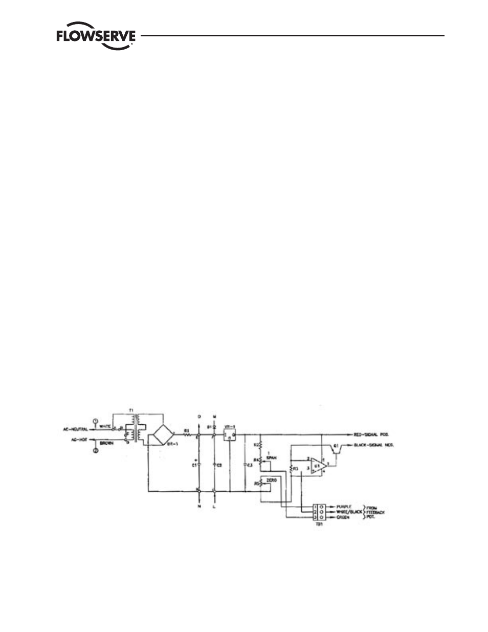
5. Repair
Schematic diagram in Figure 3 may be used for customer trouble-
shooting. If factory repair is necessary, contact factory and request
an RMA (Return Material Authorization) number. After receiving
a new circuit board, replace defective board (per instructions in
section 2) and return it to factory with description of problem and
application.
Figure 3—Wiring Schematic