3 wiring, Worcester actuation systems, Flow control – Flowserve 4 DK75 Position Output Module for DFP17 User Manual
Page 2
Flow Control
Worcester Actuation Systems
2
4 DK75 Position Output Module for DFP17
FCD WCAIM2064-00
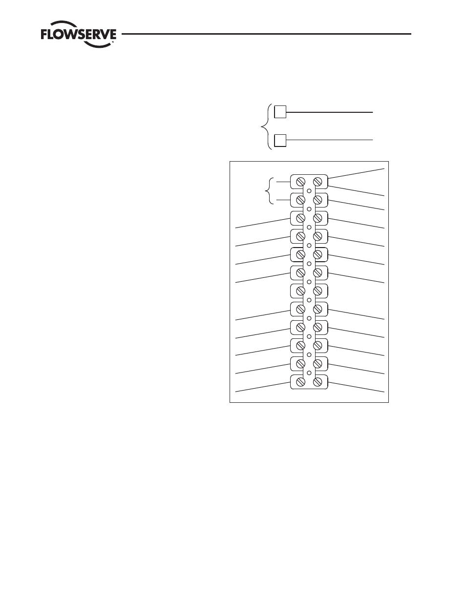
3 Wiring
(See Figures 2, 3 and 4.)
NOTE: All wiring to terminal strip should be inserted only to midpoint
of terminal strip.
For 120 VAC board only: Remove yellow wire from terminal 5 and
brown wire from terminal 6, disconnect them from N.O. contacts
of switches 1 and 2 and discard them. For all voltages: Connect
wires of output signal connector assembly from Digital Positioner
board connector (P1) such that red wire (+) is wired to terminal 6
and black wire (-) is wired to terminal 5 on the internal side of the
terminal strip.
NOTE: Check for Digital Positioner wiring diagram label inside of
cover and mark label with the 4-20 mA position output option wiring
according to appropriate wiring diagram in Figure 2.
External wiring is between actuator terminal strip and outside power
supply and various controls. Common (or negative) wire of the
power supply is wired to terminal 1 and hot (or positive) wire of the
power supply to terminal 2. An outside position indication meter is
wired with positive connection to terminal 6 and negative connection
to terminal 5.
Securely tighten all terminal screws. Secure all wires neatly with the
cable ties. Keep wiring away from all rotating parts and ensure wir-
ing is not pinched when actuator cover is installed.
The Digital Positioner board 4-20 mA position output module
has been calibrated at the factory and should require no
further adjustment.
IMPORTANT: The feedback potentiometer is calibrated for only one
90° quadrant of valve operation. If the output shaft is repositioned
to another 90° quadrant or if the output shaft is rotated a multiple
of 360° from its original position, the feedback potentiometer
will no longer be in calibration and must be recalibrated. See the
Digital Positioner Instruction, Operation and Maintenance Manual
(WCAIM2037).
Figure 2 – Wiring of DFP17 120 VAC Digital Positioner with 4-20 mA
position output
��
��
����������������
����������
�������������������������������
�
�
�������������������������������
��������
���������
��������
��������
�
�
�
�
�
�
�
��������
��������������
��������
��������������
�����������������������
��������������������
�����������������������
���������������������
������
���
��������������
��������
��������������
��������
������������������
���������������������
��������������������
����������������
����������������
������������������
��������������������
��������
��������
��������
�������
��������
�����������
������������������
�������������������
�
���������������
��������������������
�������������
��������������������
���������������
�����������
���������
�����������������
������������������
��
�����������������
��������
�����������������
�������������
��������������
���������������
���������������
�������������
���
�����
��
��
��
�
�
�
�
�
�
�
�
�
�������������������������������������������������
��������������������������������������������������