Flowserve I-75 Interface User Manual
I-75 interface, Description
Worcester Actuation Systems
1. Description
The I-75 Interface is designed to be used and mounted in the Series
75 Actuator as one of many standard options. Function of the I-75
Interface is to allow the Series 75 Actuator to be powered by a 120 or
240 VAC power supply, operated directly by any programmable
controller, microprocessor, and/or computer regardless of the output
rating of these devices. Depending on the control input to be used,
there are several options of the I-75 Interface:
These options are identified by the nameplate on the circuit board.
5V for 5 VDC input
XV for 12 VDC input
XX for 24 VDC input
15 for 120 VAC input
2. Installation of I-75 Interface Board into
Series 75 Electric Actuator
2.1 Check Kit for Parts:
Common Parts for Sizes 10-30 Actuators
Qty.
Name
1
Circuit Board Subassembly
1
Insulating Board
5-6
Washers (Nylon)
5-6
Grommets (Rubber)
5-6
Mounting Screws
5
Cable Ties
1
Wiring Label
1
Closed-End Splice
1
Wire - White
Additional Parts for Sizes 10-23 Actuators
Qty.
Name
1
Bracket - Right
1
Bracket - Left
2
Spacer (Bracket)
2
Mounting Screw (Spacer/Bracket)
Additional Parts for 240 VAC Option
Qty.
Name
2
Limit Switch
1
Lead Assembly - Gray
1
Lead Assembly - Blue
Additional Parts for Sizes 25, 30 Actuators
Qty.
Name
1
Mounting Bracket
2
Mounting Screw (Bracket)
Tools needed for assembly:
1
/
4
" Nut Driver,
1
/
8
" Screwdriver and Needle Nose Pliers.
FCD WCAIM2000-00
(Part 06094)
I-75 Interface
Installation, Operation and Maintenance Instructions
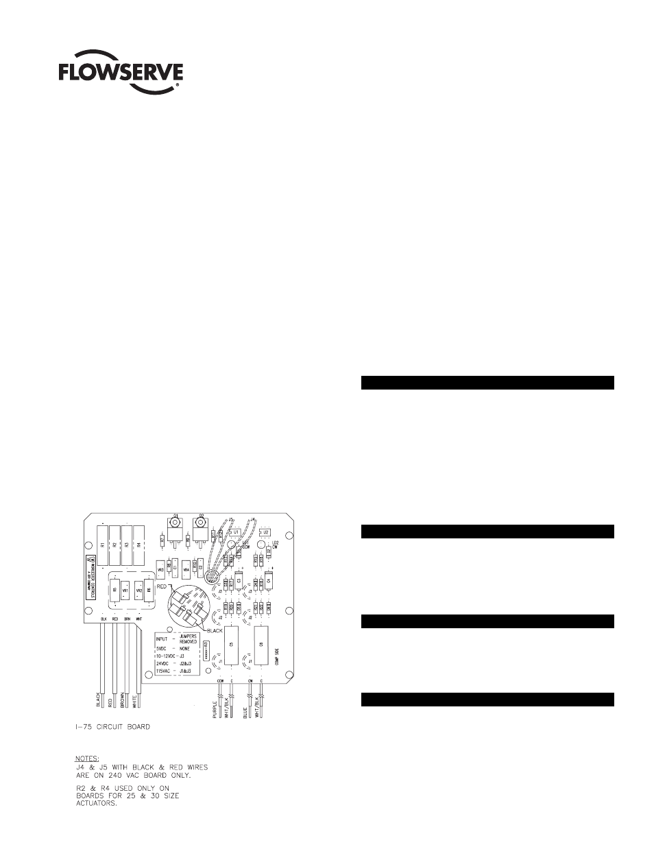
Figure 1