Wiring, Worcester actuation systems – Flowserve I-75 Interface User Manual
Page 3
3
Flow Control
Worcester Actuation Systems
3. Wiring
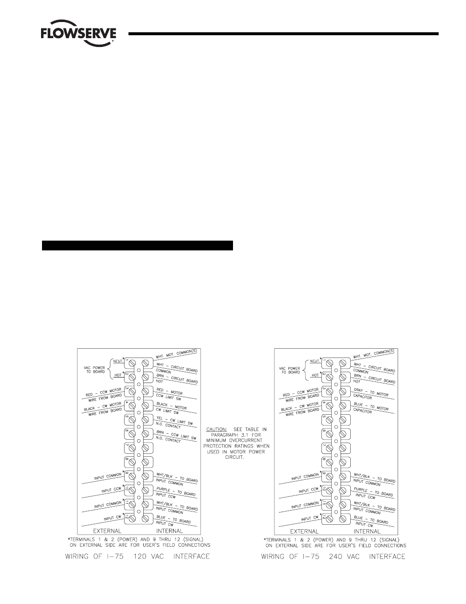
3.1 External Power - 120/240 VAC Option (Figures 3 and 4):
NOTE: All wiring to terminal strip should be inserted only to mid-point
of terminal strip.
AC power connections are made to terminals 1 and 2 of the terminal
strip. The AC neutral, or common, wire should be connected to
terminal 1 and the AC “HOT” wire to terminal 2. Grounding wire
should be connected to green colored grounding screw (if present) on
actuator base or to any base plate mounting screw in the actuator.
Signal and power wiring for an actuator may be run for short
distances in the same conduit.
See table below for minimum fuse rating when overcurrent protection
is used in motor power circuit.
Minimum Fuse Rating for Overcurrent Protection
Actuator Size
Voltage
Fuse Rating
10-23
120 VAC
5 A
25/30
120 VAC
10 A
10-23
240 VAC
3 A
25/30
240 VAC
5 A
NOTE: The table shows the minimum rating to prevent inrush current
from blowing the fuse.
3.2 External Input Signal Connections - 120/240 VAC Option
(Figures 3 and 4):
There are two isolated inputs, one for counterclockwise (CCW); the
other for clockwise (CW) directions. CCW input positive (more
positive) or hot (in case of AC) is connected to terminal 10, CW input
positive (more positive) or hot (in case of AC) is connected to
terminal 12. Other input wires, negative (less positive) or common
(in case of AC) for CCW and CW directions are connected to
terminals 9 and 11 respectively. For complete wiring diagram see
Figures 3 or 4 below, or wiring label which is to be attached to inside
of actuator cover.
3.3 Internal Wiring - Common to 120/240 VAC Options
(Figures 3 and 4):
NOTE: When there are multiple wires going to terminal 1, use the
short white wire included in kit. Connect it to terminal 1 and then
splice it to the other white wires (common) using the closed-end
splice.
From the circuit board connect white wire to the back of terminal 1,
brown wire to the back of terminal 2, red wire to the front of terminal
3, and black wire to the front of terminal 4. Connect white/black
(input common) wires of CCW and CW to back of terminals 9 and 11
respectively.
3.3.1 PC Board - 120 VAC (Figure 3):
Connect purple wire of CCW input to back of terminal 10, and
blue wire of CW input to back of terminal 12.
Figure 3
Figure 4