Electrical specifications – Flowserve APEX 4000 Pneumatic Positioner User Manual
Page 5
© 2003, Flowserve Corporation, Printed in USA
3-Position Control/Dribble Control
SR Limit Switch Method
Automax Valve Automation Systems
Installation, Operation and Maintenance Instructions
AXAIMO36-00 (AUTO-112)
07/03
Flowserve Corporation
1350 N. Mountain Springs Parkway
1978 Foreman Dr.
Flow Control Division
Springville, Utah 84663-3004
Cookeville, TN 38501
www.flowserve.com
Phone: 801 489 8611
Phone: 931 432 4021
Max. Voltage
Min. Voltage
Max. Current
Model
Agency Approvals
Hazardous Location Rating
1
(VDC)
(VDC)
(mA)
4000
None
None
NA
NA
NA
4100
None
None
30 VDC
6 VDC
150 mA
4200
FM
(EX) Cl. 1, Div. 1, Gr. B-D
30 VDC
6 VDC
150 mA
CSA
(EX) Cl. 1, Div. 1, Gr. B-D
30 VDC
6 VDC
150 mA
4300
DMT
(EX) EEx d IIC T4-T6
3
30 VDC
4
6 VDC
50 mA
4
FM
(IS) Cl. 1, Div. 1, Gr. A-D
28 VDC
4
6 VDC
50 mA
4
4400
2
CSA
(IS) Cl. 1, Div. 1, Gr. A-D
28 VDC
4
6 VDC
50 mA
4
SCS
(IS) Ex I 1 G EEx ia IIC T6
3
30 VDC
4
6 VDC
110 mA
4
TÜV
(IS) Ex II 2 G EEx ia IIC T6
3
28 VDC
4
6 VDC
60 mA
4
Warning: These instruments must be installed in accordance with local and national electrical codes, especially for hazardous locations.
Consult unit label to determine specific unit certifications.
Notes:
1
See hazardous location certificate for detailed temperature ratings. All Apex 4000 units comply with ATEX directive for non-electric
equipment intended for use in hazardous locations to EX II 2 G.
2
Additional information regarding entity parameters and instructions for wiring to intrinsically-safe I-P may be found in separate IOM, as
well as in the hazardous location certificate.
3
See hazardous location certificate for special conditions for safe use.
4
Maximum voltage and current considerations may be affected by application specifics, such as choice of barrier, ambient temperatures,
etc. See hazardous location certificate for additional information.
Electrical Specifications:
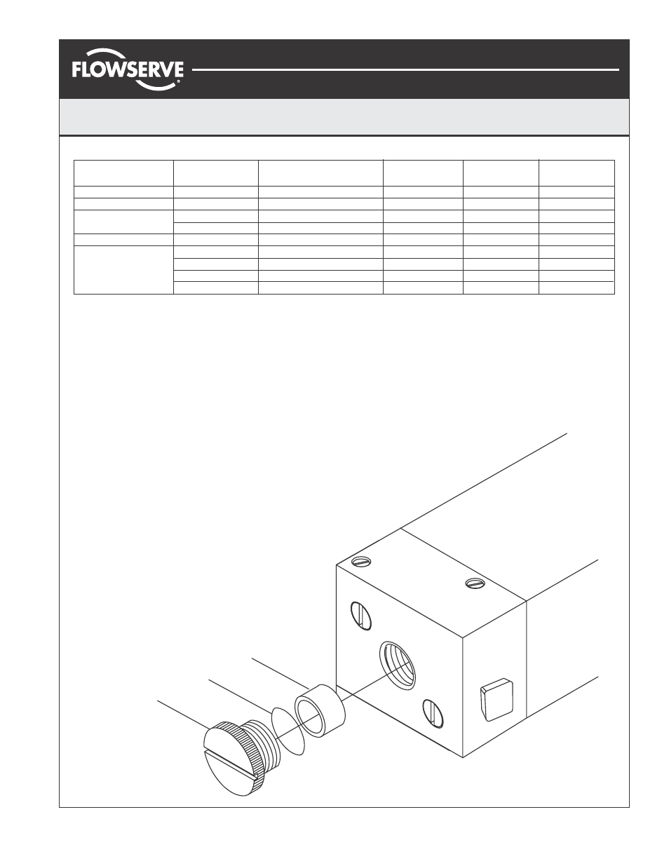
Filter Plug Replacement:
Caution:
Do not operate the unit without filter and filter
plug installed. Do not attempt to unscrew filter plug while
positioner is pressurized.
Note:
This filter is not designed to act as a permanent
source of clean, dry air.
1.
Remove air supply pressure from positioner.
2.
Unscrew filter plug (1) and O-ring.
3.
Remove filter (3) and inspect filter and filter compart-
ment. If moisture is found, check upstream filters and
oil-water separators. Moisture can cause I-P failure.
4.
Replace filter if necessary and reinstall.
Page 5 of 8
1
2
3