Flowserve SNA-Series Pneumatic Actuator User Manual
Page 2
FCD AXAIM0004-
01
(AUTO-4)
03/
11
Page: 2 of 4
©
2011, Flowserve Corporation, Printed in USA
3-Position Control/Dribble Control
SR Limit Switch Method
Flowserve Corporation
1350 N. Mountain Springs Parkway
1978 Foreman Dr.
Flow Control Division
Springville, Utah 84663-3004
Cookeville, TN 38501
www.flowserve.com
Phone: 801 489 2233
Phone: 931 432 4021
Automax Valve Automation Systems
Installation, Operation and Maintenance Instructions
Changing Number of Spring
1. Follow the Disassembly Procedures through step 6.
2. Determine nested spring combination of inner, middle and outer
springs. Consult catalog torque charts, distributor or factory. Insert
appropriate springs into cylinder. Springs must be properly seated
against piston and endcap to assure that springs do not bind.
3. Re-assemble the actuator.
➁ S50 has maximum of 2 springs
per endcap
➂ Install springs on opposite sides
Note
:
➀ #1 Spring has one color code dot
#2 Spring has two color code dots
#3 Spring has three color code dots
Spring chart SNA063-SNA200
Spring Combination ➀
Spring Group
#1 Spring
#2 Spring
#3 Spring
(inner)
(middle)
(outer)
4
2
5
1➂
1➂
6
2
7
1
2
8
2
2
9
1➂
1➂
2
10
2
2
11
1
2
2
12
2
2
2
Spring chart SNA050 ➁
Spring Combination ➀
#1 Spring
#2 Spring
#3 Spring
(inner)
(low rate outer) (high rate outer)
4
1➂
1➂
5
2
6
2
1
7
1
2
8
2
2
9
2
2
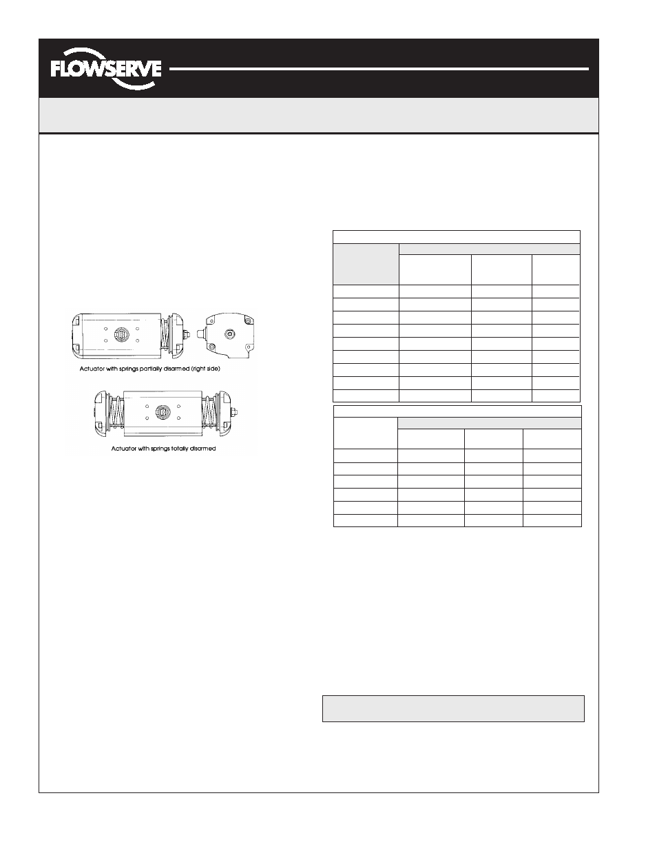
CAUTION:
Follow step 4 to relieve force on inward
travel stop before proceeding.
To remove Spring Return endcap, first completely remove
two diagonal Endcap Screws (21) from one endcap. The two
remaining endcap screws should be removed evenly. As the
screws are removed, the springs will push the endcap out.
Repeat for opposite side. The springs will be totally unloaded
before the screws are completely unthreaded. Remove the
springs (23,24,25).
Double Acting Actuator: Remove the 8 endcap screws (21).
Step (7) will push the endcaps (18,19) from the body (1).
7. Rotate Pinion (3) counterclockwise (DA & SR-FCW) or
clockwise (DR & SR-FCCW) to drive the pistons (2) off the
end of the rack. Pull the left piston (2) from the body (1) by
pulling on the stop bolt (9).
8. Remove the right piston (2) by pushing out through inside of
Body (1).
9. Remove the pinion snap ring (5) and pinion washer (4).
10. Tap pinion (3) lightly with plastic mallet to remove.
Reassembly Procedures
1. Inspect all parts for wear and replace any worn parts as
needed. Replace all O-rings.
2. Clean all components and lightly grease cylinder bore, pinion
and seals per temperature rating notes (page 4).
3. Reverse the disassembly procedures to reassemble.
4. The standard Pinion (3) orientation is with the drive pocket
parallel with the body (1) in the CW position.
5. When fitting the Pistons (2) ensure the teeth engage the
Pinion (3) at the same time by measuring in from the edge of
the body (1) the same distance from each end. Note: The
orientation of the pistons will determine the operation of the
actuator. Refer to the diagrams under Operation for correct
piston position.
6. Test the actuator for smooth operation and air leakage at
service pressure before reinstalling.
5. Exhaust air from Port 2, the Stop Bolt (9) should now turn
freely. Continue turning Stop Bolt (9) clockwise until it it is
disengaged from the Endcap.
6. Spring Return Actuator:
Changing Pinion Orientation
Note: Steps 4&8 are not required for DA actuator.
1. Disconnect all air and electrical supplies from actuator.
2. Remove all accessories from actuator and dismount actuator
from valve.
3. Position actuator with air supply ports facing you.
4. Follow step 6 under disassembly procedure to unload spring
pressure from right endcap (18) only.
5. Remove the Pinion Snap ring (5) and Pinion Washer (4).
6. Tap Pinion (3) lightly with plastic mallet to remove.
Caution:
Failure to follow step 4 will result in permanent damage to SR actuator.
7. Reverse steps 5&6 with new pinion (3) orientation.
8. Assembly right endcap (18) in reverse order of disassembly.
Grease endcap screw (21) threads with multipurpose “polymer”
fortified grease, such as Dubois Chemical MPG-2, before
assembly.