Flowserve WXCL UltraSwitch User Manual
Page 2
A ground screw is also included. Simply wire the solenoid to auxiliary terminals, then connect power leads to the
opposite terminal side. Be sure to properly ground the solenoid at provided ground terminal.
UltraSwitch™ XCL series enclosures include two 3⁄4" NPT conduit entries and the XML series includes two
M25x1.5 conduit entries. Installation shall be per National Electric Code,
local codes, and manufacturers’
instructions. In all cases, environmental seals must be used to protect against ingress of water through the
conduit.
Special Hazardous Location Instructions:
For North America installations you must install a conduit sealing fitting within 18 inches of the enclosure to meet
NEC regulations.
For ATEX and IECEx installations an appropriately rated Cable Gland is required. Any unused conduit entry must
have a suitably rated blanking element.
CAUTION:
Substitution of components may impair suitability for Zone 2 Increased Safety.
Do not disconnect equipment unless power has been switched off or the area is known to be non-hazardous.
Cleaning this housing by rubbing should be done in a non-hazardous area.
Potential electrostatic charging hazard, clean only with a damp cloth
– danger of propagating discharge.
All grounding and bonding installation requirements must be addressed
All installation, inspection, and maintenance of the equipment should be performed by suitably trained
personnel. In addition, for ATEX, all installation, inspection, maintenance and repair must be done by suitably
trained personnel. For more information refer to EN 60079-14:1997, EN 60079-17, EN 60079-19
Replacement parts not to invalidate certification and to be only obtained direct from the manufacturer.
Adjusting Limit Switches:
Ultra
Switch™ enclosures feature quick-set cams which are used to trip the limit switches. These cams are easily
adjusted without tools. Caution: disconnect power before removing cover when installed in hazardous
locations. Remove cover and set aside. Rotate actuator/valve to full clockwise (CW) position. Adjust cam(s)
associated with CW as follows:
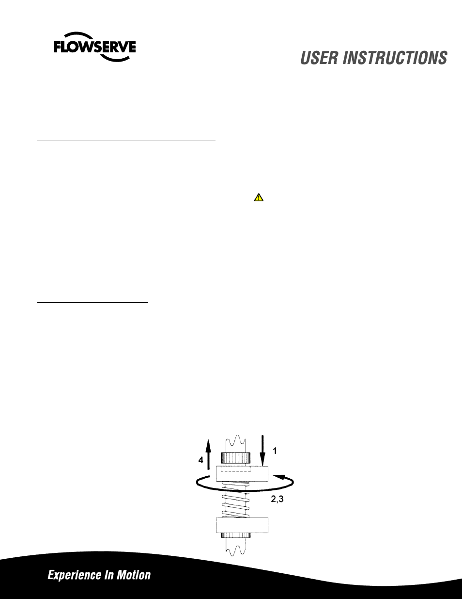
1. Push or pull cam against spring to disengage it from splines.
2. Rotate cam CW breaking contact with switch (or moving magnet away from switch).
3. Continue rotating cam CW just until switch trips.
4. Release cam and reengage it with splines.
Rotate actuator/valve to full counterclockwise (CCW) position. Adjust cam(s) associated with CCW as described
insteps 1 through 4, except rotate cam(s) CCW.
Note: factory setting is top switch = CW (closed), second switch = CCW (open), third switch = CW, and fourth
switch = CCW.