Flowserve DC AF-17 Electronic Positioner User Manual
Dc af-17 electronic positioner, A. general, B. cautions
Worcester Actuation Systems
WCAIM2050
DC AF-17 Electronic Positioner
Installation, Operation and Maintenance Instructions
A. GENERAL
This supplement to the AC AF-17 IOM covers the DC AF-17 circuit
board. This supplement will cover those features of the DC board
that are different than the AC version.
There are two major differences between the AC and DC versions of
the AF-17 board. The first of these is the fact that the DC AF-17
board is plug connected to the actuator terminal strip as opposed to
being wired directly into the terminal strip. This makes it much
easier to install or remove the circuit board for adjustments, repairs,
etc. The baseplate in the 75 Series Actuator is wired differently for
the DC versus the AC AF-17 board, and the two are not
interchangeable. The DC baseplate has connector plug assemblies
wired into the terminal strip, and the limit switches are wired into the
connector plug assemblies. The second major difference is that this
board is powered directly with DC voltage versus AC voltage. This
board can be powered with either 12 or 24 volts DC with no changes
needed to the circuit board. The only caution in this regard is that
the proper motor(s) be used for the voltage applied.
IMPORTANT: All of the cautions and notes in the AC AF-17 IOM
should be read prior to installing this board in a 75 Series Actuator.
B. CAUTIONS
PLEASE READ THIS SECTION
1. Power Rating
At this time, the DC AF-17 board has been approved for use in
size 10 through 23 75 Actuators only.
2. NOTE: Fusing Protection for input circuits as found on earlier DC
boards only.
Earlier version of DC AF-17 boards are protected with a 62 mA
fuse (F2) and a 12 volt zener diode (CR18) installed across the
input circuit. These two devices in combination are designed to
protect the CMOS chip from both an overvoltage condition and
reverse polarity of the input signal. For earlier version using a
4-20 mA signal input circuit, the signal input impedance of the
AF-17 board is approximately 220 ohms which means that it
only takes about 4.5 volts to drive 20 mA through the input
circuit. If your current source is capable of outputting 12 volts
or more, it may be necessary to place a
¹ ₄ watt resistor in
series with the current loop to drop the excess voltage,
otherwise you might find that you keep blowing the input
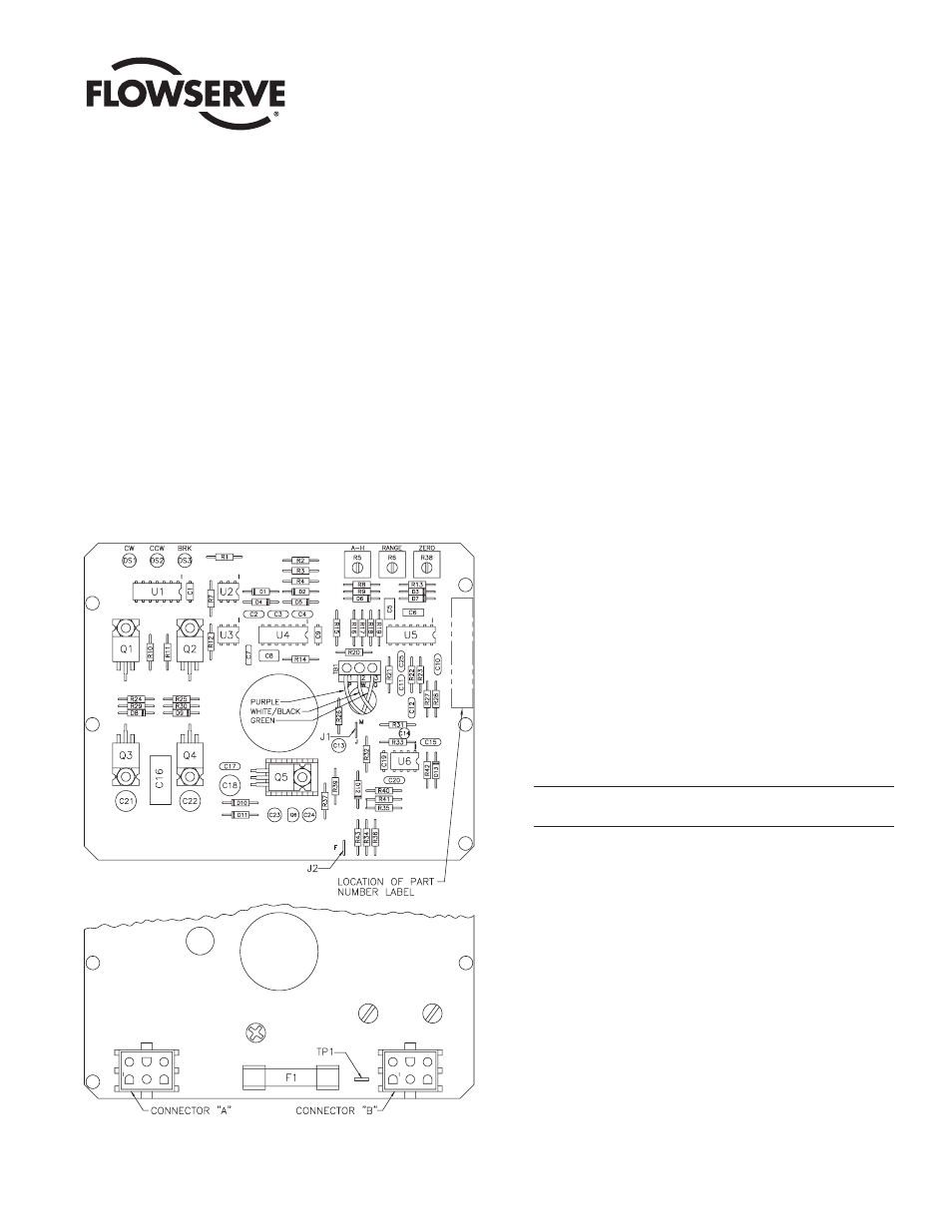
Use or value of components R13, R26, R34, R35, R36, J1 and J2
will vary depending on circuit board input.
Figure 1 – 12 and 24 VDC Positioner Circuit Board