Worcester controls – Flowserve 90 Series Feedback Potentiometer User Manual
Page 3
3.CALIBRATION FOR “P” OR “D”
(SINGLE OR DUAL POTENTIOMETER)
OPTION
Prior to adjusting the potentiometer, the M.A.S. package must be
mounted to the actuator, and the baseplate must be installed in the
M.A.S. Unit. Adjust the potentiometer pinion gear so that there is
approximately
Z\zn" tooth engagement between the face gear and the
pinion gear and tighten the pinion gear set screw. The actuator must
be in the full-closed position prior to making the potentiometer
adjustment. In the case of a double-acting actuator, either temporarily
connect air to the appropriate actuator port or use a wrench to move
the actuator to the closed position. Unless there is air supplied to a
spring-return actuator, it should automatically be in the closed
position. Using an ohmmeter, measure the resistance between the
purple and the white/black potentiometer leads at the terminal strip.
Rotate the face gear to obtain a resistance on the ohmmeter of 80 to
90 ohms.
Note: It is not necessary to loosen or remove face gear snap ring to
rotate gear.
Important: The feedback potentiometer is calibrated for only one 90-
degree quadrant of valve operation. If the output shaft is repositioned
to another 90-degree quadrant, or if the output shaft is rotated a
multiple of 360 degrees from its original position, or if the M.A.S.
package is removed from the actuator, the feedback potentiometer will
no longer be in calibration and must be recalibrated as directed above.
If the dual potentiometer is being installed in a positioner unit (that
previously contained a single potentiometer), the positioner will require
recalibration.
4.CALIBRATION FOR “4”
(4-20 MILLIAMP POSITION
INDICATOR) OPTION
a. For Non-Positioner/Controller
Calibrate the potentiometer per Section 3 above.
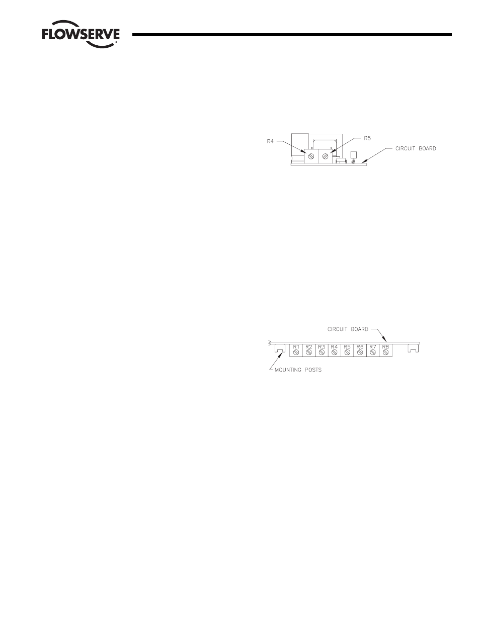
To obtain proper 4 to 20 milliamp output, the indicator circuit
board potentiometers R4 and R5 must be calibrated as follows:
• Connect an ammeter to terminals 4 (positive) and 5 (negative).
• Place the actuator in its closed (full-clockwise) position and
adjust R5 (adjacent to the “4” etched on the circuit board) to
indicate 4 mA on the meter.
• Place the actuator in its open (full-counterclockwise) position
and adjust R4 (adjacent to the number “20” etched on the circuit
board) to indicate 20 mA on the meter.
Note: Adjustment of one potentiometer affects the other. Repeat
the procedure several times to reach the proper values.
b. For Positioner/Controller
Calibrate the potentiometer per Section 3.
To obtain proper 4 to 20 milliamp output, the indicator circuit
board potentiometers “4 mA” (R2) and “20 mA” (R1) must be
calibrated as follows:
• Connect an ammeter to terminals 4 (positive) and 5 (negative).
• Place the actuator in its closed (full-clockwise) position and
adjust R2 to indicate 4 mA on the meter.
• Place the actuator in its open (full-counterclockwise) position
and adjust R1 to indicate 20 mA on the meter.
Note: Adjustment of one potentiometer affects the other. Repeat
the procedure several times to reach the proper values.
WCAIM2042
Feedback Potentiometer and 4-20 mA Position Indicator for Series 90 Modular Accessory System
3
Flow Control Division
Worcester Controls