Worcester actuation systems, Flow control – Flowserve 180 Rotation Center-Off Kit User Manual
Page 2
Flow Control
Worcester Actuation Systems
2
180° Rotation, Center-Off Kit for 10-30 75 Electric Actuator
FCD WCAIM2074-00
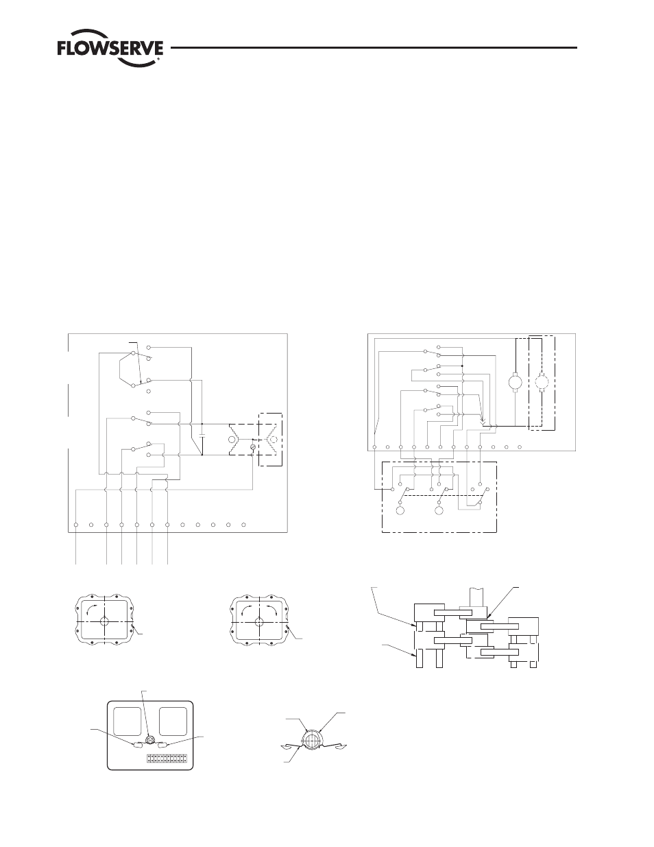
II. Installation of the Center-Off Switch and Wiring
Wiring Notes: All wiring to terminal strip should be inserted
only to midpoint of terminal strip. Grounding wires should be
connected to green-colored grounding screw (if present) on
actuator base or to any baseplate mounting screw in actuator.
A. The 180° center-off switches’ lever arms will be located in
the same direction as the existing limit switches’ lever arms.
B. For 10-23 75 Actuators:
Remove the screws holding down the existing actuator limit
switches. Place the spacers provided in the kit between the
existing actuator limit switches (use straight lever arms) and
the new center-off limit switches (use hooked lever arms).
Replace and tighten the limit switch screws securely back
into position. (See diagram for switch identification.)
For 25-30 75 Actuators:
Remove the screws holding down the existing actuator
switches. Be sure the existing spacers remain under the
switches.
Place the spacers provided in the kit between the existing
actuator limit switches (use straight lever arms) and the new
center-off limit switches (use hooked lever arms). Replace
the limit switch screw with new longer screws (4-40 x 1½)
and securely tighten switches in their proper position. (See
diagrams for switch identification and spacer location.)
SEE ENLARGED VIEW "A"
MOTOR
SWITCH 3
SWITCH 4
(IF USED)
MOTOR
1 2 3 4 5 6 7 8 9 10 11 12
OVERSIZE FOR
CAM 3
(SHOWN SLIGHTLY
PICTORIAL CLARITY)
CAM 4
LIMIT SWITCH
LEVER
0°
N.P.T. CONDUIT
OPENING
OPEN
90°
CLOSED
4
3
CAM
2
CAM
1
CAM
CAM
4 PLACES
SWITCH SPACER
SW-2
SW-4
SW-3
SW-1
SPACER
2 PLACES
SPACER
25/30 ONLY
T
SPECIAL
SWITCHES
& CAMS
STANDARD
SWITCHES
& CAMS
{
{
WIRING
EXTERNAL
WIRING
INTERNAL
RED
N.O.
23
THRU
SIZES
ONLY
20
C
D
BLACK
C
C
N.O.
N.C.
SW-3
N.O.
N.C.
C
C
SW-1
N.C.
N.O.
N.C.
SW-2
SW-4
HELD CLOSED
11
10
12
8
7
6
ORANGE
5
4
3
BLAC
K
YELLOW
BROW
N
OPEN
CW
OPEN
CLOSE
INDICA
TION
CLOSE
INDICA
TION
CENTER-OF
F
POSITIO
N
9
2
1
WHIT
E
NEUTRA
L
COMMON
RE
D
CCW
SWITCHES
SPECIAL
& CAMS
SWITCHES
STANDARD
& CAMS
{
{
BLUE
C
C
SW-4
BLACK
RED
N.C.
N.O.
N.O.
SIZE
22
12
11
ONLY
GRAY
BLUE
BLUE
C
10
9
BLU
E
8
GRA
Y
7
ORNG
.
BLUE
SW-3
SW-2
C
SW-1
6
BRN.
4
YEL. 5
3
BLK.
2
RED
C
N.C.
N.C.
N.O.
N.O.
N.C.
CENTER
CW
CCW
+
_
RED
1
BLACK
PROVIDED BY CUSTOMER
3P ROTARY SWITCH RECOMM.
CENTER-OFF POSITION
1ST DIVERT
90°
OPENING
POSITION
0°
N.P.T. CONDUIT
2ND DIVERT
POSITION
180°
180° Center-off Actuator
Series 75 W. X & Z Shown
Standard 90° Actuator
Series 75 W. X & Z Shown
1. Switch configuration is as shown above
(When viewed from the terminal strip
side of the actuator).
2. Actuator shown at 0° position (all the way CW).
3. Cam settings are as follows:
Switch 1. Opens at 0°. Controls
1st divert position.
Switch 2. Opens at 180°. Controls
2nd divert position.
Switch 3. Opens at 89°. Controls
center-off position from
1st divert position.
Switch 4. Opens at 91°. Controls
center-off position from
2nd divert position.
Note: 1. Switches 1 and 2 and cams 1 and 2
are standard. Switches 3 and 4 and
Cams 3 and 4 are center-off type.
2. Use cam spacer as needed to line up
Cam and switch.
Typical View Showing Location of
Center-off Cams & Limit Switches
Set Up at the Center-off Position
VIEW A
AC
DC