Flowserve 39 Series Rotary Limit Switch Kit User Manual
Installation, Mounting the switch, Wcaim2035
Worcester Controls
WCAIM2035
(Part 17400)
Series 39 Rotary Limit Switch Kit (Male Output Shaft)
Installation, Operation and Maintenance Instructions
INSTALLATION
Included in the Rotary Limit Switch Kit (RLK) is a Rebuild/Accessory
Addition label which is to be marked and applied to actuator after RLK
has been installed.
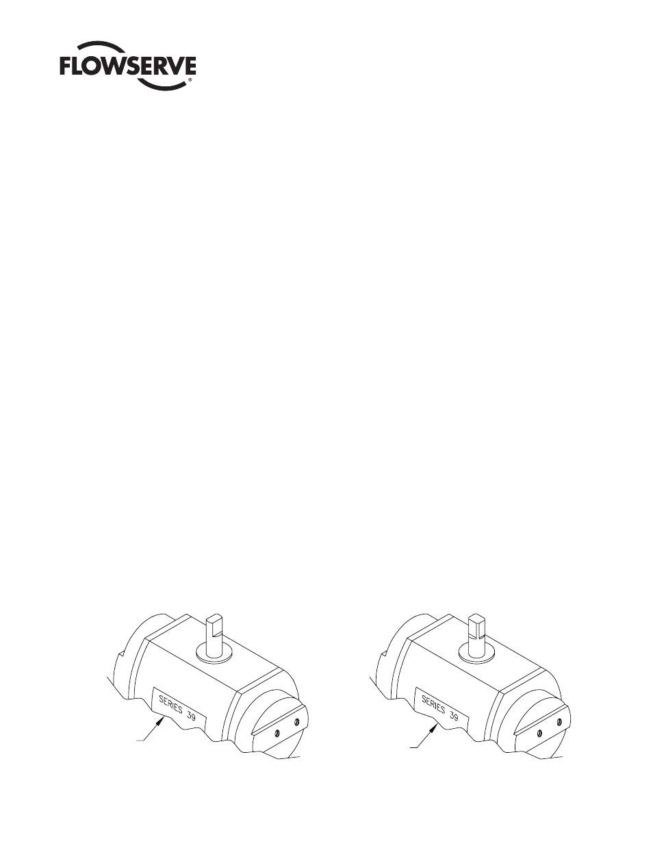
The top of the actuator is determined by the nameplate being read
“right-side-up.” Actuator sizes 10, 15 and 20 use a double-flatted
output shaft (the top flats being oriented 90 degrees to the bottom
flats), while sizes 25 through 50 use a square (cross-sectional) output
shaft. (See figures A and B.)
NOTE: For series “39” actuators ONLY: The 2539-5039 cannot be
cross-line mounted.
The normal method of mounting is to have the actuator in-line with
the pipe line and the valve and actuator in the “FAIL-CLOSED”
position.
For “FAIL-CLOSED” cross-line operation (10–20 sizes), invert actuator
and cross-line mount actuator to pipe line.
For “FAIL-OPEN” in-line operation (10–20 sizes), cut pip off top
bearing of actuator if bracket does not allow for attaching actuator
(Rev. 1 actuators only). Place valve in open position. Invert actuator
and mount in-line with pipe line. NOTE: If in-line coupling is used,
actuator does not need to be inverted.
For “FAIL-OPEN” cross-line operation (10–20 sizes), cut pip off of
bottom bearing if required (as noted above). Place valve in open
position, mount actuator cross-line to pipe line.
MOUNTING THE SWITCH
1. Remove the position indicator (if any) from actuator shaft.
2. Actuator should be in the “closed” position.
3. Position mounting bracket (1) onto actuator. Firmly secure with
four (4) screws (2) and lockwashers (3) supplied with the
mounting kit.
NAMEPLATE
NAMEPLATE
Sizes 10 through 20
Sizes 25 through 50
Figure A
Figure B