Switch adjustments, Wiring, Worcester controls – Flowserve 39 Series Rotary Limit Switch Kit User Manual
Page 2
Flow Control Division
Worcester Controls
Flowserve Corporation has established industry leadership in the design and manufacture of its products. When properly selected, this Flowserve product is designed to perform its intended function
safely during its useful life. However, the purchaser or user of Flowserve products should be aware that Flowserve products might be used in numerous applications under a wide variety of industrial
service conditions. Although Flowserve can (and often does) provide general guidelines, it cannot provide specific data and warnings for all possible applications. The purchaser/user must therefore
assume the ultimate responsibility for the proper sizing and selection, installation, operation, and maintenance of Flowserve products. The purchaser/user should read and understand the Installation
Operation Maintenance (IOM) instructions included with the product, and train its employees and contractors in the safe use of Flowserve products in connection with the specific application.
While the information and specifications contained in this literature are believed to be accurate, they are supplied for informative purposes only and should not be considered certified or as a guarantee of
satisfactory results by reliance thereon. Nothing contained herein is to be construed as a warranty or guarantee, express or implied, regarding any matter with respect to this product. Because Flowserve
is continually improving and upgrading its product design, the specifications, dimensions and information contained herein are subject to change without notice. Should any question arise concerning
these provisions, the purchaser/user should contact Flowserve Corporation at any one of its worldwide operations or offices.
For more information about Flowserve Corporation, contact www.flowserve.com or call USA 1-800-225-6989.
FLOWSERVE CORPORATION
FLOW CONTROL DIVISION
1978 Foreman Drive
Cookeville, Tennessee 38501 USA
Phone: 931 432 4021
Facsimile: 931 432 3105
www.flowserve.com
© 2003 Flowserve Corporation, Irving, Texas, USA. Flowserve and Worcester Controls are registered trademarks of Flowserve Corporation.
WCAIM2035 10/03 Printed in USA
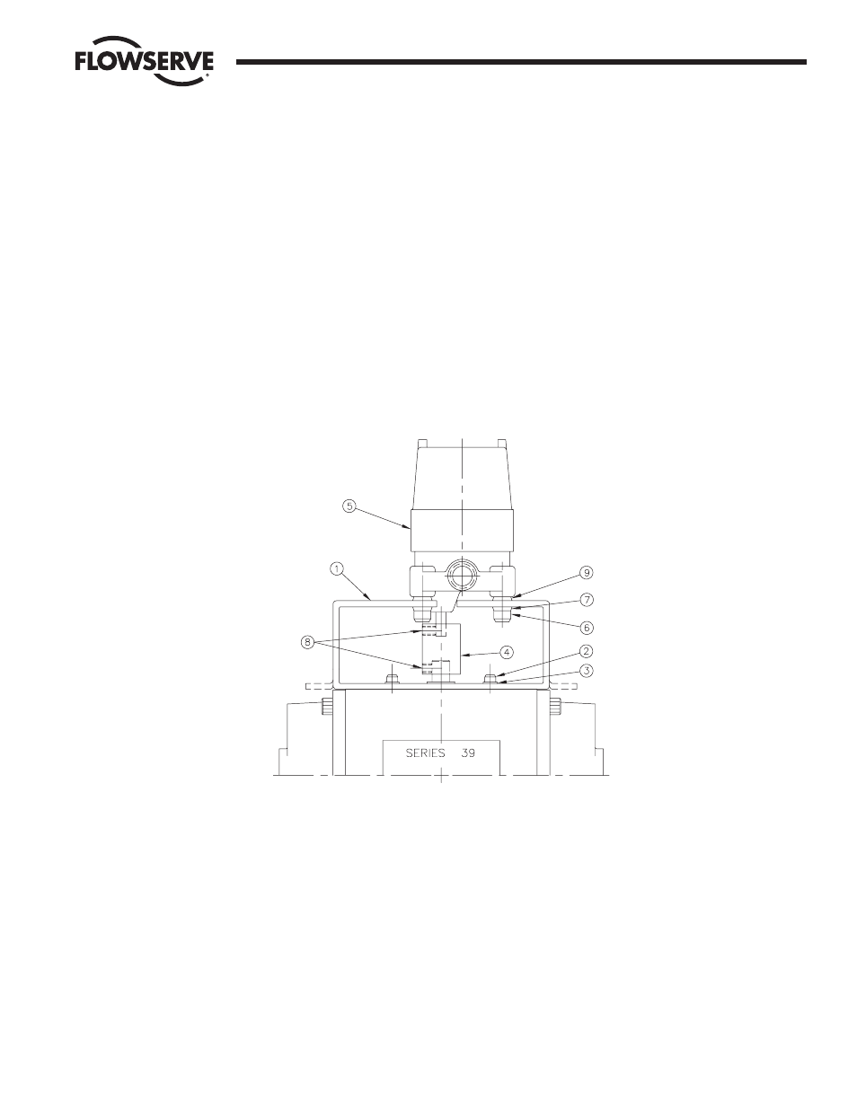
4. Place coupling (4) over shaft of actuator and align it with the
shaft. Install and slightly tighten the lower set screw (8) provided.
5. Place switch (5) and four (4) rubber washers (9) onto mounting
bracket. Align flat of the switch input shaft with upper set screw
hole in the coupling and slide switch shaft into the coupling (4).
Install and slightly tighten the set screw (8) provided.
6. Secure limit switch with four (4)
C|,"-24 cap screws (6) and
lockwashers (7), and slightly tighten cap screws (6) at this time.
7. Firmly tighten the two (2) coupling set screws (8).
8. Manually cycle actuator before wiring switch, for proper
alignment.
9. After manually cycling actuator, firmly tighten (but do not
overtighten) the four (4) cap screws (6). Also, ensure that the two
(2) coupling set screws (8) are tight.
NOTE: When actuator is inverted 180˚ and mounted on valve, the
switch is installed in the same manner as described above.
SWITCH ADJUSTMENTS
Detailed switch adjustment procedures are described on an
Instruction Sheet provided with each switch. The actuator should be
placed in the position in which switch indication is desired
(Open/Closed) and then these instructions should be followed.
WIRING
Wiring should be installed in accordance with prevailing electrical
codes.