Flow control module, Block and bleed module, Maintenance – Flowserve APEX 5000 Positioner NAMUR Accessories User Manual
Page 2: Ordering information
B00065 (AUTO-70) 4/00
Page: 2 of 2
© 2000, Flowserve Corporation, Provo, UT
Automax Valve Automation Systems
Installation, Operation and Maintenance Instructions
Flow Control Module:
Adjustments to flow control module settings should be
made with the valve package in service and under normal
operation. To slow operation moving away from start or
fail position, tighten (cw) adjustment screw closest to
positioner supply port (output port 1). To slow operation
moving towards start or fail position, tighten (cw) adjust-
ment screw furthest from positioner supply port (output
port 2). Note: Figures 2 and 3 show flow characteristics
for adjustment screw positions.
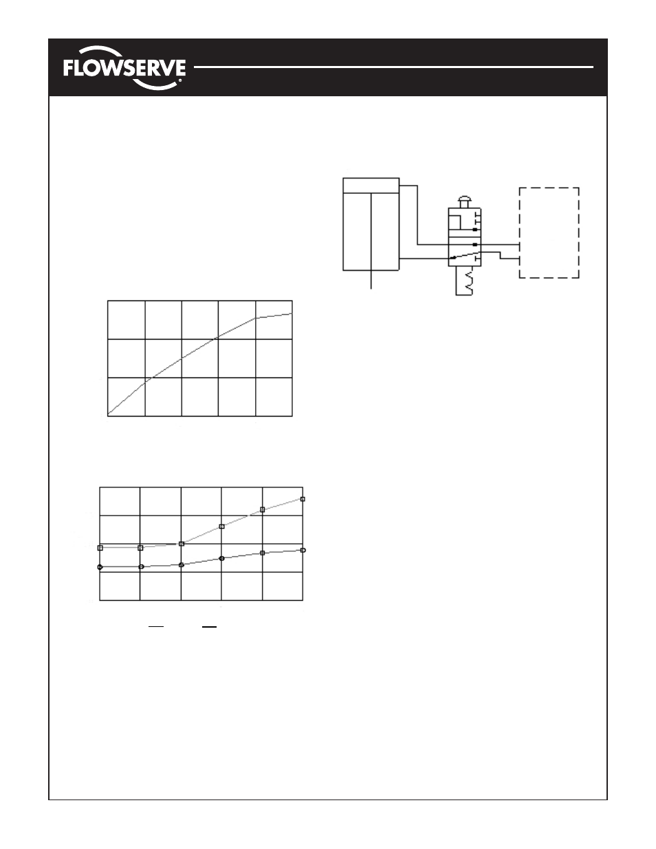
Figure 2 - Exhaust Flow Characteristics
Figure 3 - Inlet Flow Characteristics
Figure 4 - Block & Bleed Module Schematic
Block and Bleed Module:
With plunger in (as shown), module is in normal mode and
will not interfere with operation. To block positioner and
bleed actuator, pull plunger out.
Maintenance:
There are no serviceable parts in any NAMUR accessory,
nor is there a need for maintenance. However, periodic
checks for proper operation should be made.
Ordering Information:
Specify kit numbers KMFC for flow control module, KMBB
for block and bleed module, and KMBBFC for both mod-
ules. Consult factory for other options.
BLOCK &
BLEED
MODULE
APEX
5000
ACTUATOR
15
10
5
0
0
1
2
3
4
5
Turns (ccw)
SCFM at 100 psig
40
30
20
10
0
0
1
2
3
4
5
Turns (ccw)
O
50 psig
■
■
100 psig
SCFM at 100 psig