Flowserve SNA250 User Manual
Flowserve Hardware
©
2005, Flowserve Corporation, Printed in USA
Automax Valve Automation Systems
Installation, Operation and Maintenance Instructions
Flowserve Corporation
1350 N. Mountain Springs Parkway
1978 Foreman Dr.
Flow Control Division
Springville, Utah 84663-3004
Cookeville, TN 38501
www.flowserve.com
Phone: 801 489 2233
Phone: 931 432 4021
FCD AXAIM0005-00 (LMR0014-1) (AUTO-5) 03/05
Page 1 of 4
SNA250 / SNA300
MODEL
SNA250
SNA300
(DA & SR)
27.32
32.60
180°
39.14
44.00
B
4.250
5.000
C
5/8 - 11x.63
5/8 - 11x.86
D
2.87
N/A
E
1.850
N/A
F
1.81
2.50
G
11.02
13.39
H(NPT)
1/2
1/2
J
5.91
6.30
K
11.02
13.39
L
1.181
1.181
M
5.118
5.118
N➁➂
10 - 24
10 - 24
O
Ø
2.20
2.44
P
1.969
1.969
PP
0.98
0.98
Q
Ø
3.75
3.75
R
1.65
1.65
S
0.24
N/A
Wts. lbs. (DA)
137
217
Wts. lbs. (SR)
172
288
Volume
(IN
3
) CW
757
1403
Volume
(IN
3
) CCW
720
1019
Notes:
➀ Actuators shown in the full clockwise (CW) position as viewed from
the accessory side.
➁ Accessory mounting holes not for gear override or stop block.
Consult factory.
➂ Use studs only to mount. Bolts are not recommended.
④ Air consumption per 90° = V Supply Pressure + 14.7
(Standard cubic feet) 1728 14.7
(
)
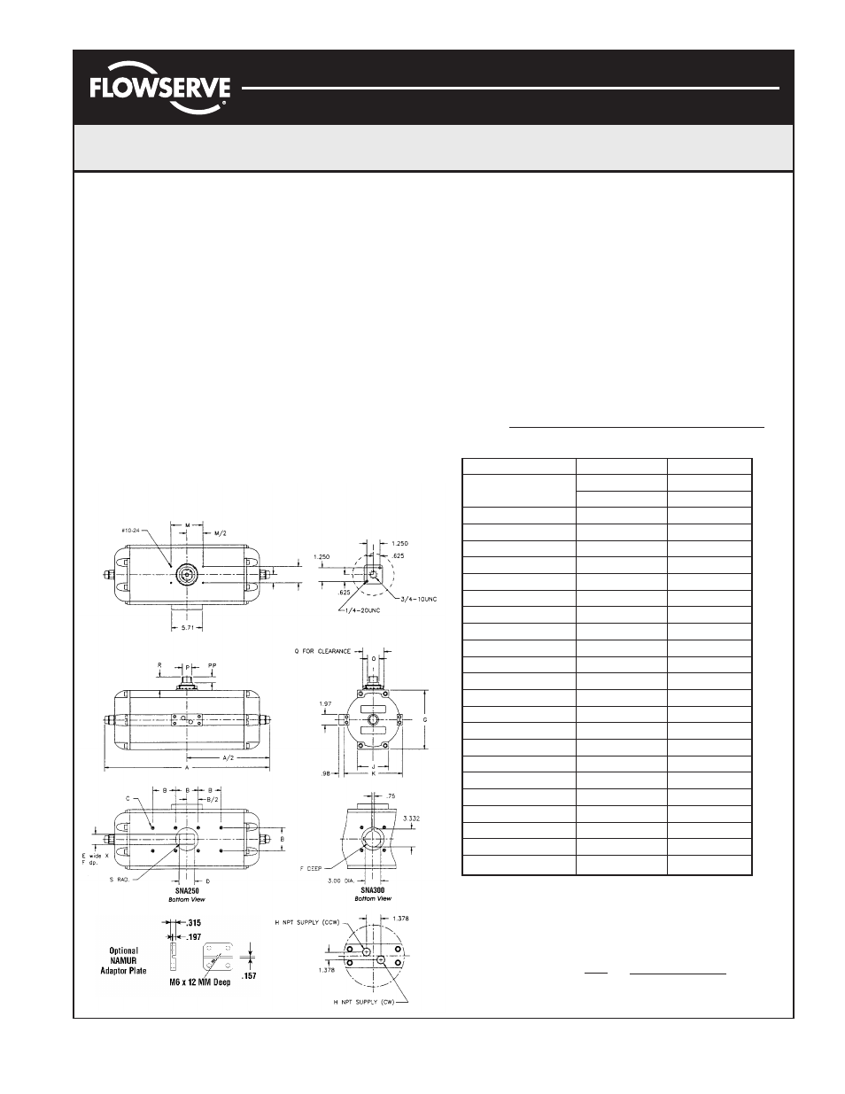
Dimensional Information
All actuators are factory lubricated for life, but still should be
protected from the elements and stored indoors until ready for
use. The ports of the actuator are plugged as supplied from
the factory. If actuators are stored for a long period of time
prior to installation, the units should be stroked periodically
to prevent the seals from taking a set.
Prior to assembly, check the mounting surfaces, the stem
adaptor and the bracket to assure proper fit. Manually open
and close the valve to insure freeness of operation. Be sure
the valve and Automax actuator rotate in the same direction
and are in the same position (i.e., valve open, actuator open).
Secure the valve with the stem vertical. Bolt the bracket to the
valve and place the stem adaptor on the valve stem. Position
the actuator over the valve and lower to engage the stem
adaptor to the actuator shaft.
Continue to lower until the actuator seats on the bracket
mounting surface. In order to align the bolt holes, it may be
necessary to turn or stroke the actuator a few degrees and/or
adjust the actuators travel stops. Bolt the actuator to the bracket.
After consulting the valve manufacturer’s recommendations,
adjust the travel stop bolts of the actuator for the proper open
or closed valve position. Adjust the Stop Bolt (8) until the
desired travel is obtained and reinstall O-ring (10) and Nut (9).
Pneumatically stroke the actuator several times to ensure
proper operation with no binding of the stem adaptor. If the
actuator is equipped with an UltraSwltch or other accessories,
adjust them at this time.
To prolong actuator life use only clean, dry plant air. Lubricated air is
not required, however it is recommended particularly for high cycle
applications.
CAUTION: Do not use lubricated air with positioners.
A
L/2
L