Flowserve Heavy Duty Gear Override User Manual
Heavy duty gear override, Heavy duty gear overrides, Installation
Flowserve Corporation
765 South 100 East
Phone: 801 373 3028
Flow Control Division
Provo, Utah 84606
Facsimile: 801 489 2228
www.flowserve.com
Email: [email protected]
Automax Valve Automation Systems
Installation, Operation and Maintenance Instructions
B00101-1 03/00
Page 1 of 2
© 2000, Flowserve Corporation, Provo, UT
Heavy Duty Gear Overrides
Gear overrides on Automax heavy duty actuators provide
an easy, durable method for manually operating the actu-
ator. The gear overrides are declutchable for efficient,
automatic operation. The gear override consists of a
declutchable gear mounted to the accessory side of the
actuator. Any accessories, such as limit switches and
positioners, may be offset mounted. The gear override is
designed for the full rated torque of the actuator.
Installation
Automax standard gear overrides are provided as a com-
plete integral component of the heavy duty actuator. Gear
override units are shipped with the gear mounted to the
actuator and shut-off & vent valves installed on the pres-
sure cylinder. No additional customer installation is
required. See Automax Heavy Duty IOM (B00032) for
instructions on installing Heavy Duty actuator into service.
To retrofit gear override onto existing heavy duty actuator,
existing torque shaft must be replaced with override
torque shaft.
1. Disconnect air pressure and electrical power from
actuator. Remove all accessories from actuator and
dismount from valve.
2. Loosen stop bolt jam nut and back off clockwise stop
bolt to remove spring cartridge preload. Refer to
Heavy Duty IOM (B00032) for cross-sectional view of
parts.
3. Remove the bearing retainer screws from the valve
mounting side and slide the retainer plate off the
shaft.
4. The torque shaft may now be tapped out using a soft
faced hammer. Use care not to drop the shaft or the
bearing when they come out.
5. Reverse steps 3 and 4 with manual override torque
shaft. Orientation of the torque shaft is unimportant,
since it is symmetrical.
To install gear override to heavy duty actuator with
manual override torque shaft:
1. Assemble bracket and coupler provided with gear
override field mounting kit to the accessory side of
the actuator.
2. Mount gear override to actuator in orientation shown
below. Gear override should be declutched. To
declutch, lift declutching handle out of slot and
rotate 90 degrees.
3. Add shut-off and vent valves to actuator per operat-
ing schematic (see back).
4. Mount any accessories to actuator and test in auto-
matic mode.
Note: After mounting actuator to valve, the gear override
travel stops must be set. Make sure that the actuator
travel stops are set correctly. Then set the gear over-
ride travel stops at the same position.
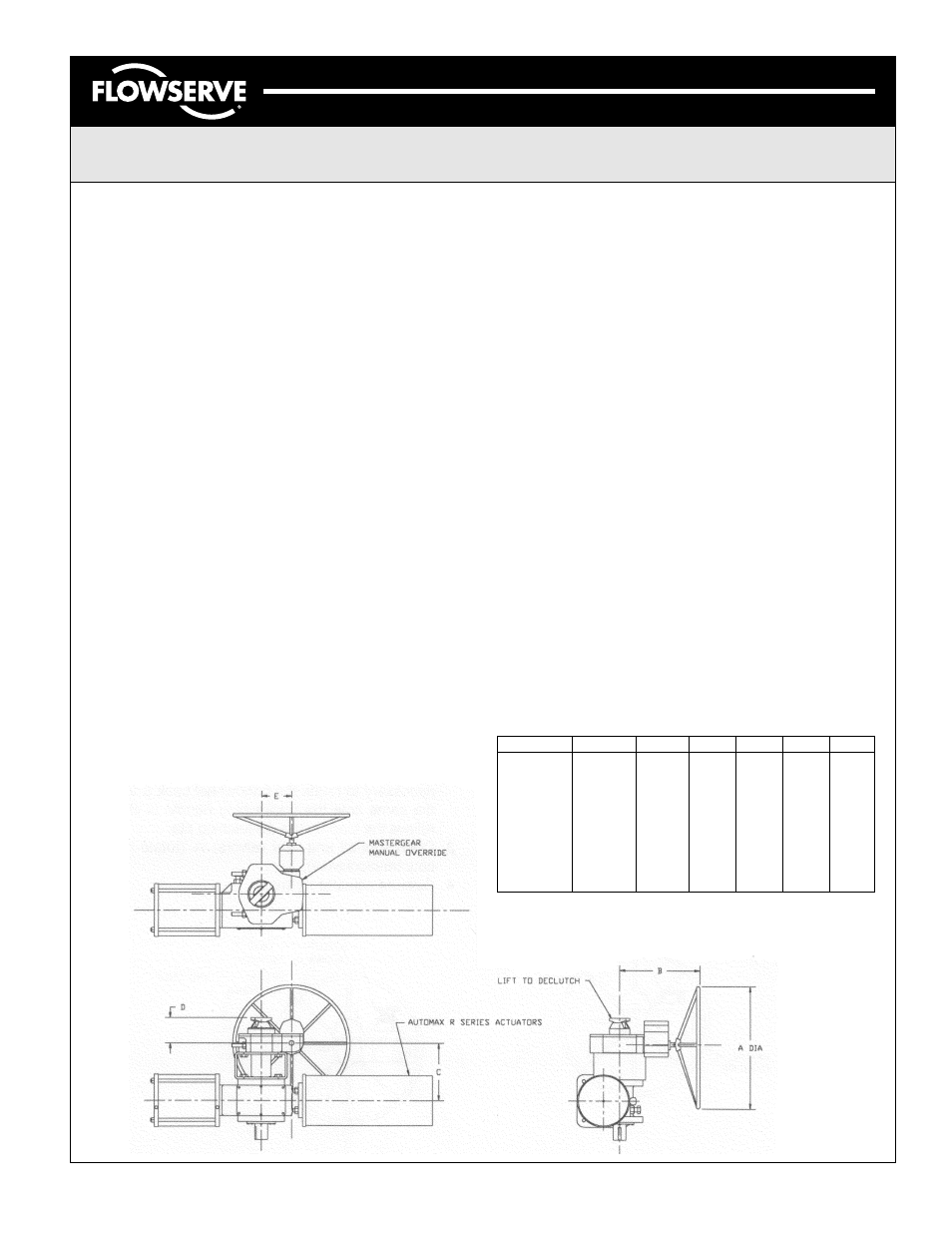
GEAR MANUAL OVERRIDE DIMENSIONAL DATA
NOTES:
1) ACTUATOR IS SHOWN IN THE FULL CLOCKWISE POSITION AS VIEWED FROM
THE ACCESSORY SIDE.
2) FOR COMPLETE ACTUATOR MOUNTING DIMENSIONS SEE PNEUMATIC
ACTUATORS CATALOG.
Heavy Duty Gear Override
ACTUATORS
OVERRIDE
A
B
C
D
E
R2
C24
24.00
10.44
7.80
4.69
3.02
R2
D30
30.00
12.94
8.00
5.69
3.38
R2
E30
30.00
12.94
8.13
5.88
4.38
R2
F24
24.00
16.21
8.13
5.88
1.31
R3
G30
30.00
18.33
12.00
6.03
2.31
R3
H30
30.00
18.71
13.08
6.19
2.11
R3
J30
30.00
19.33
12.63
10.37
2.68
R4
H30
30.00
18.71
15.77
6.19
2.11
R4
J30
30.00
19.33
15.32
10.37
2.68
R4
K36
36.00
19.96
15.32
10.75
3.81
R4
L36
36.00
23.33
15.57
10.65
9.33