Interface wiring – Flowserve DC Motor Controller Board User Manual
Page 3
3-Position Control/Dribble Control
SR Limit Switch Method
Flowserve Corporation
1350 N. Mountain Springs Parkway
1978 Foreman Dr.
Flow Control Division
Springville, Utah 84663-3004
Cookeville, TN 38501
www.flowserve.com
Phone: 801 489 8611
Phone: 931 432 4021
Automax Valve Automation Systems
Installation, Operation and Maintenance Instructions
LME0005-1 (AUTO-43) 07/03
©
2003, Flowserve Corporation, Printed in USA
Page 3 of 4
A.
PLC Open Collector Outputs are also known
as discrete digital ouputs. The "output on"
state causes a zero volt measurement at TB1
signal and RET terminals. The "output off" state voltage
will equal approximately 5.00V at TB1 terminals.
B.
Dry-Contact Switching, while using manual or
relay control, does NOT require external
voltages to be applied to contacts. When
contacts are closed, the voltage between the
TB1 signal and RET terminals will equal zero volts.
Open contact voltage will equal approximately
5.00V at TB1 terminals.
C.
3-Way Manual Switching is similar to dry-
contact switching, as discussed above in
Step B, but allows one single pole, 3 position
manual switch to control direction and braking
at a remote jogging station.
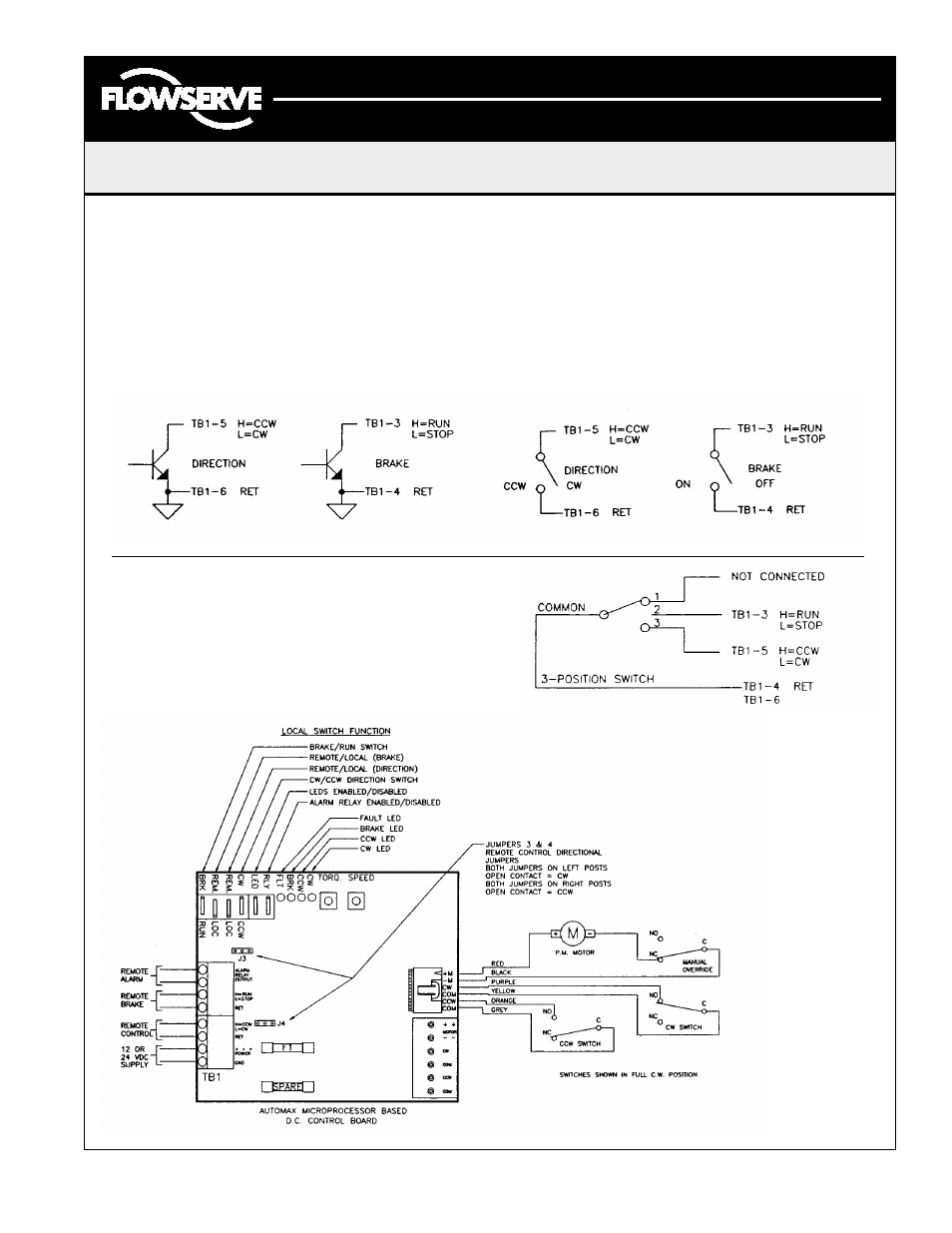
DC Motor Controller Board Layout and Motor Interface Wiring
Interface Wiring
Control Input Configurations
PLC TTL OUTPUT CONFIGURATION
OPEN COLLECTOR (O.C.)
DRY CONTACT SWITCHING
SPST SWITCH OR RELAY
ABOVE DIAGRAMS REPRESENT JUMPERS J3 & J4 ON LEFT TWO POSTS
POSITION
1:
BRAKE OFF, CW ROTATION
POSITION
2:
BRAKE ON, NO ROTATION
POSITION
3:
BRAKE OFF, CCW ROTATION