Troubleshooting, Wiring diagrams – Flowserve CPL Series CENTURA User Manual
Page 3
LME0009-1 (Auto-39) 04/03
©
2003, Flowserve Corporation, Printed in USA
3-Position Control/Dribble Control
SR Limit Switch Method
Flowserve Corporation
1350 N. Mountain Springs Parkway
Phone: 801 489 8611
Flow Control Division
Springville, Utah 84663-3004
Facsimile: 801 489 2228
www.flowserve.com
Automax Valve Automation Systems
Installation, Operation and Maintenance Instructions
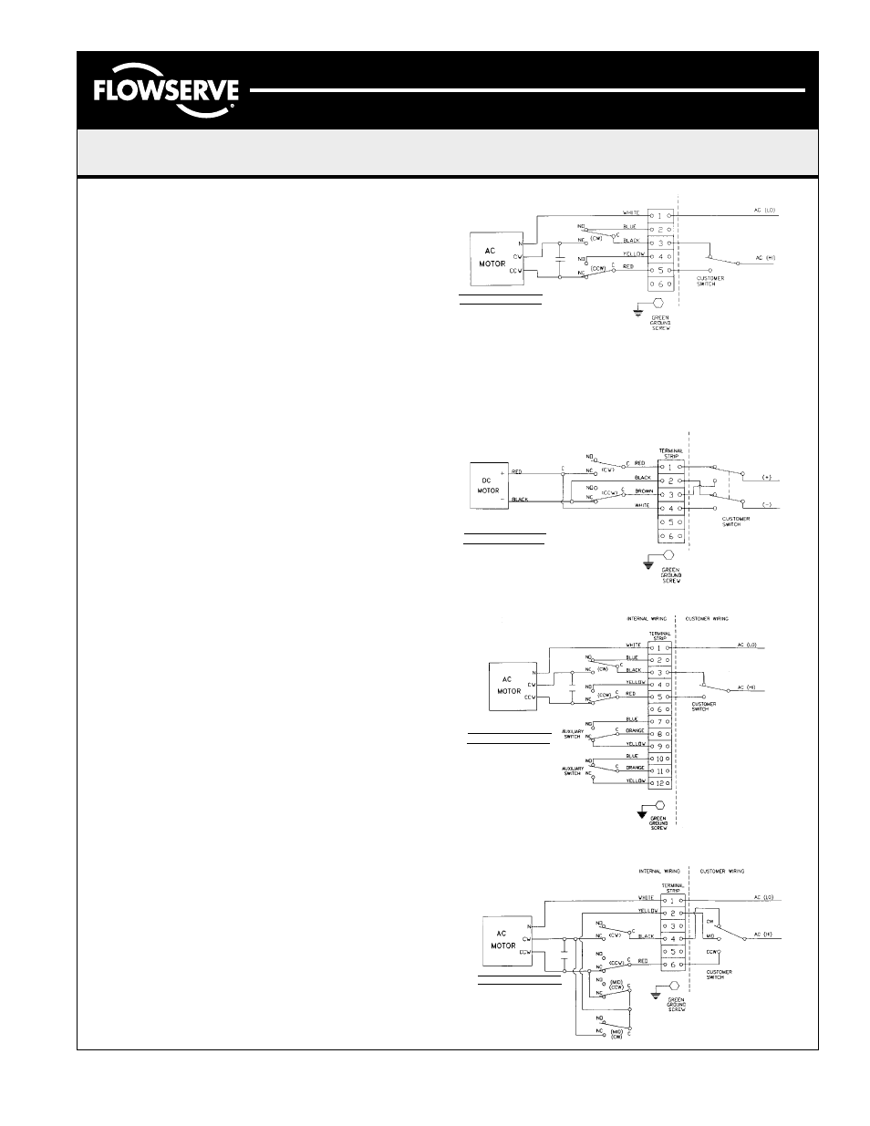
Reversible D. C. Actuator
Reversible A. C. Actuator with 2 extra switches
Reversible A. C. Actuator wired for 3 position
Troubleshooting
Problem:
There is power to the unit, but it does not respond.
Solution:
Check the nameplate to see that the correct voltage has
been applied.
Check the wiring to see that it is per the wiring schematic.
Check the limit switches to see if they are in the normal
operating range.
Problem:
Power is getting to the motor, but it merely hums.
Solution:
Check to see that the proper voltage is applied.
Make sure all the connections are tight.
Check to see that CW and CCW power connections are not
powered at the same time.
Problem:
The actuator performs erratically.
Solution:
Check to see that the actuator is not stalling.
Check the ambient temperature rating. The permanent split
capacitor units are equipped with thermal cut-outs. Excessive
temperatures and cycle frequencies may heat the motor up and
the thermal cut-out turns it off.
Wiring Diagrams
Notes:
1. Consult factory when wiring multiple actuators in series or
parallel, serious damage may result.
2. Wiring diagrams show internal wire connections and
suggested customer connection for proper use. Switches
shown in "customer wiring" are for illustration only and are
not supplied with the actuator.
SYMBOLS & DESCRIPTIONS
1. WHITE - Motor Common.
2. BLUE - Full CW Position
Indicator
3. BLACK - AC Hi will Turn
Actuator CW.
4. YELLOW - Full CCW
Position Indicator.
5. RED - AC Hi will Turn
Actuator CCW.
NO - Normally Open
NC - Normally Closed
C - Common
SYMBOLS & DESCRIPTIONS
SYMBOLS & DESCRIPTIONS
SYMBOLS & DESCRIPTIONS
1. RED - DC+ (CW)
2. BLACK - DC- (CW)
3. BROWN - DC+ (CCW)
4. WHITE - DC- (CCW)
NO - Normally Open
NC - Normally Closed
C - Common
NO - Normally Open
NC - Normally Closed
C - Common
1. WHITE - Motor Common.
2. BLUE - Full CW Position
Indicator.
3. BLACK - AC Hi will Turn
Actuator CW.
4. YELLOW - Full CCW
Position Indicator.
5. RED - AC Hi will Turn
Actuator CCW.
6. ORANGE - Switch Common.
1. WHITE - Motor Common.
2. YELLOW - AC Hi will Turn
Actuator to MID.
4. BLACK - AC Hi will Turn
Actuator CW.
6. RED - AC Hi will Turn
Actuator CCW.
NO - Normally Open
NC - Normally Closed
C - Common
Page 3 of 4
Reversible A. C. Actuator
NO - Normally Open
NC - Normally Closed
C - Common
TERMINAL
STRIP