Installation – Flowserve FPS 14 User Manual
Page 3
Installation
Consult the Installation Drawings for the proper piping configuration for your application.
Please call GESTRA if you are not sure of the
proper configuration.
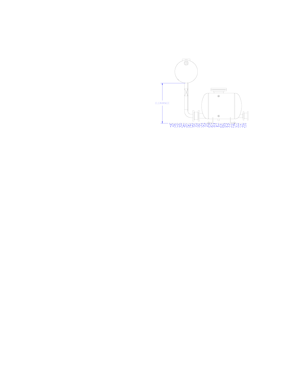
1. CLEARANCE: Install the pump below the
equipment to be drained. Proper clearance is
required for the pump to fill. The clearance is
the distance between the base of the pump
and the bottom of the equipment to be
drained. The FPS 14 and FPS 23 require a
minimum clearance of 36”.
2. CHECK VALVES: Install the check valves on
the pump tank, with gaskets, making sure the
check valves are installed in the same
direction. The flow direction has been stamped on each check valve and should match the flow
arrow on the front of the tank.
a. Install lower flange bolts and secure with nuts and lock washers.
b. Place the check valve between the flanges from above onto the bottom bolts. Verify the
flow arrows are pointing in the correct direction.
c. Install and center the gaskets on both sides of the check valves.
d. Install the remaining flange bolts, nuts, and lock washers. Tighten evenly in a star pattern.
NOTE: The correct bolts for the different check valves are as follows:
1” RK16A (S.S.)
1/2”-13x3-1/2” (FPS-366)
1” RK44 (Bronze)
1/2”-13x3”
(FPS-193)
2” RK16A (S.S.)
5/8”-11x4-1/2” (FPS-313)
2” RK44 (Bronze)
5/8”-11x6”
(FPS-034)
3” RK16A (S.S.)
5/8”-11x6”
(FPS-034)
3” RK44 (Bronze)
5/8”-11x5”
(FPS-071)
e. Connect piping from discharge check valve flange to the condensate return line or other
discharge point
Full Port Isolation Valves are recommended on the pump inlet and outlet to allow the pump to
be isolated for service.
Pressure Gauges are recommended upstream and downstream of the pump for accurate
measurement of actual operating conditions.
NOTE: All isolation valves must be full port in order to achieve rated pump capacity.
3. MOTIVE GAS SUPPLY: Connect the motive gas supply (steam, air, or gas) to the ½” NPT
connection “P” on the top of the cover flange. The motive gas supply line should have a
strainer and a steam trap (GESTRA MK series for steam service) or liquid drainer trap (GESTRA
UNA series for air or gas service) installed before the pump. See installation drawings for the
proper piping of the components for the motive supply.
A Pressure Gauge should be installed on the motive gas supply to verify that there is sufficient
motive gas pressure at the pump. If steam is being used, a siphon loop (pigtail) should be
installed before the pressure gauge.