Operation, 1 use of the phantom, 2 data interpretation and analysis – Fluke Biomedical 18-216 User Manual
Page 7
Operation
Use of the Phantom
2
2-1
Section 2
Operation
2.1 Use Of The Phantom*
1. Place the pattern at the desired height above the breast support plate, either with no extraneous
materials between the bar pattern and the breast support, or with a homogeneous phantom
supporting the pattern. Position the pattern within 1 cm of the chest wall edge of the image
receptor, centered laterally. It is important that the test pattern be positioned in a reproducible
manner. A test stand or jig may be helpful.
2. Place the image receptor in the location where it would normally be used for mammography, (i.e., in
the cassette holder for contact mammography.) If a stationary grid is normally used with the
imaging system, remove it to avoid moire patterns.
3. Select the kVp, mA, and focal spot used for
imaging an average breast during normal
radiography and an exposure time that will
produce a background optical density from 1.2 to
1.6. This may be done either manually or in the
AEC mode.
4. Make an exposure and process the film.
5. Repeat steps 1 through 6 for other focal spots
and other geometries. In magnification mode, the
bar pattern should be positioned 4.5 cm above
the magnification breast support. Be sure to
record the magnification factor.
2.2 Data Interpretation And Analysis*
1. Under masked conditions, view the high-contrast resolution pattern images with 10x to 30x
magnification.
2. Note the highest frequency pattern with lines that are distinctly visible throughout at least half of the
bar length (for a bar pattern) and record the highest frequency visible for each test image.
2.3 Suggested Performance Criteria And Corrective Action*
In the contact mode, measurements made with the bars parallel to the anode-cathode axis should be at
least
13
Ip/mm; measurements with the bars perpendicular to the anode-cathode axis should be at least
11
Ip/mm. In magnification mode, the limiting spatial resolution should be no lower than the above
specifications.
.
If the above specifications are not met, remove the compression paddle and the grid and retest (while
maintaining geometry consistent with that before). If the results are still below the above specifications, a
more detailed investigation of the reason should be made using a slit camera.
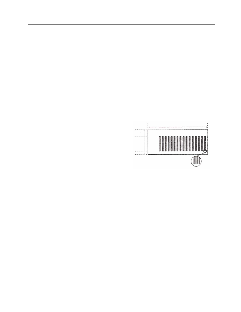
5 6 7 8 9 10 11 12 13 14 15 16 17 18 19 20
28 mm
8 mm
20 Line Pair/mm Test Target